
Chain tensioner based on cam, and control method thereof

A technology of tensioner and cam, which is applied in the direction of belt/chain/gear, mechanical equipment, transmission device, etc., can solve the problem of not effectively attenuating the frequency and amplitude of chain beating, affecting the service life of chain transmission efficiency, and not reducing the chain The number of beatings and other problems can be reduced to reduce the excessive amplitude of beating, the structure is simple, and the effect of easy installation is achieved.

Inactive Publication Date: 2016-03-23
LIAONING UNIVERSITY OF TECHNOLOGY
View PDF6 Cites 5 Cited by
  • Summary
  • Abstract
  • Description
  • Claims
  • Application Information

AI Technical Summary

Problems solved by technology

Although there are various structures of chain tensioners on the market, some chain tensioners cannot effectively reduce the number of chain jumps and weaken the range of chain jumps during the chain transmission process while ensuring the tension and guiding functions. Affect the transmission efficiency of the chain and its own service life
At present, the commonly used chain tensioner adopts an automatically adjustable spring structure, which can automatically adjust the pre-tightening degree of the chain in time as the chain itself jumps and wears, but it cannot effectively attenuate the frequency and frequency of the chain jump during the chain transmission process. Amplitude

Method used


Image

  • Chain tensioner based on cam, and control method thereof
  • Chain tensioner based on cam, and control method thereof
  • Chain tensioner based on cam, and control method thereof

Examples


Embodiment Construction

[0040] The present invention will be further described in detail below in conjunction with the accompanying drawings, so that those skilled in the art can implement it with reference to the description.

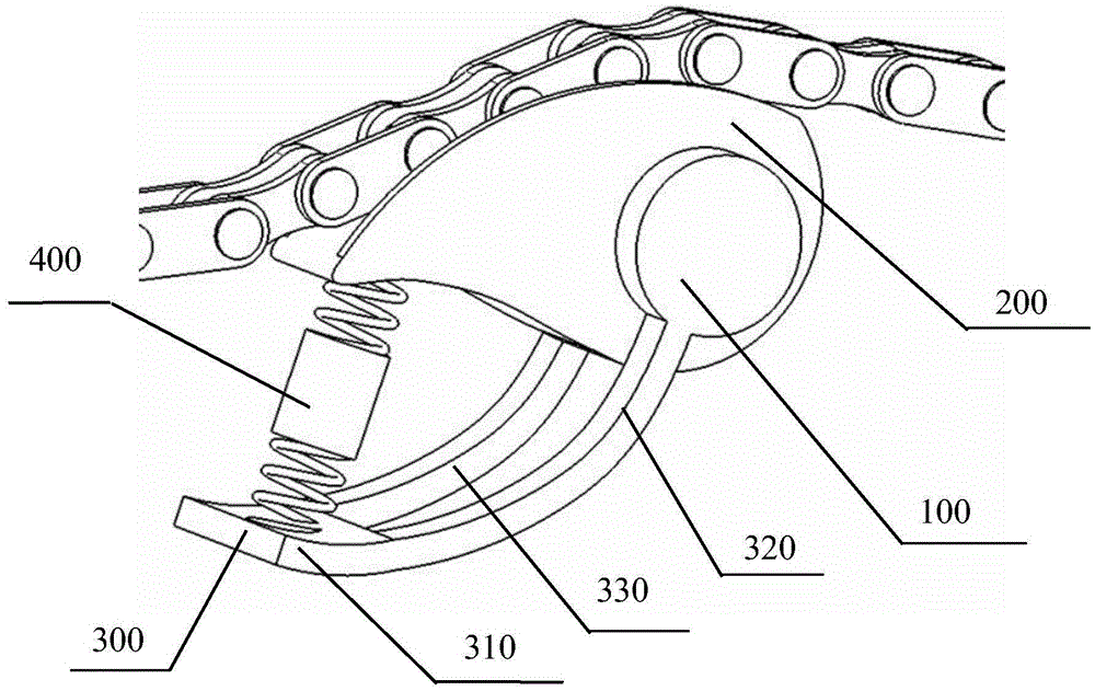
[0041] Such as figure 1 As shown, the cam-based chain tensioner provided by the present invention includes: a fixed shaft 100 , a tensioning cam 200 , a support arm 300 and a shock-absorbing support device 400 .

[0042] Wherein, the fixed shaft 100 is fixed and plays a fixed role, and torsion springs are arranged on both sides of the fixed shaft to ensure that the chain runs more smoothly during the transmission process.

[0043] One end of the tensioning cam 200 is sleeved on the fixed shaft 100, and can swing around it. The outer side of the tensioning cam 200 is provided with a smooth groove for placing a chain. The base circle part of the tensioning cam 200 is concentric with the fixed shaft 100, and It can swing around the fixed shaft 100, and the outside of the cam li...


PUM


Abstract

The invention discloses a chain tensioner based on a cam. The chain tensioner comprises a fixing shaft, the tensioning cam, a supporting arm, a first extending arm, a second extending arm, and a shock absorption supporting device, wherein the tensioning cam is arranged on the fixing shaft in a sleeving manner and can swing around the fixing shaft, and a smooth groove is formed in the periphery of the tensioning cam and used for containing a chain; the supporting arm comprises a common terminal; the first extending arm and the second extending arm which are both connected to the common terminal are symmetrically arranged, and the first extending arm and the second extending arm are fixed to the two ends of the fixing shaft; and one end of the shock absorption supporting device is supported on the common terminal of the supporting arm, and the other end of the shock absorption supporting device is supported at the far end of the tensioning cam and used for flexible supporting to the tensioning cam. The invention further provides a control method of the chain tensioner based on the cam. By changing the current intensity of an electromagnetic body, the chain is made in an optimal tensioned state.

Description

technical field [0001] The invention relates to a chain tensioner, in particular to a cam-based chain tensioner and a chain tensioner control method. Background technique [0002] Tensioners are commonly used retaining devices on chain or belt drive systems. The tensioner acts on the transmission chain or transmission belt, tensions and guides the transmission chain or transmission belt, and keeps it in the best tension state all the time. The chain or belt will be deformed and elongated due to its own stress and wear during long-term use, resulting in a reduction in the transmission efficiency of the chain or belt. In order to keep the chain or belt at an appropriate tension, that is, not to skip teeth due to looseness and not to be damaged due to over-tightening, a set of suitable tensioning devices is required to keep them at an appropriate tension. Therefore, the quality of the tensioner directly affects the quality and transmission efficiency of the chain or belt powe...

Claims


Application Information

Patent Timeline
IPC IPC(8): F16H7/08
CPCF16H7/0829F16H2007/0863F16H2007/0893
Inventor 屈小贞刘丛浩关亮亮孙晓帮孙乃振
Owner LIAONING UNIVERSITY OF TECHNOLOGY
Learn More