Leakage detecting device of high-temperature flange connecting system

A connection system, high temperature flange technology, used in flange connection, pipe/pipe joint/pipe fitting, through components, etc., can solve the problem that non-bolt connection can not be tested, affect the normal force of gaskets, and high equipment cost problem, to achieve the effect of low cost, simple structure and high measurement accuracy

Inactive Publication Date: 2016-03-23
WUHAN INSTITUTE OF TECHNOLOGY +1
View PDF8 Cites 5 Cited by
  • Summary
  • Abstract
  • Description
  • Claims
  • Application Information

AI Technical Summary

Problems solved by technology

However, the existing leak detection device can only test the leakage rate of the bolted flange connection system, and cannot test the non-bolted connection, and the existing leak detection device also has the following problems: the existing leak detection device uses two One way is to maintain the pressure of the closed pipeline by adding gas to the closed pipeline, and the supplementary amount is the leakage amount. This method is difficult to operate and the cost of equipment is high. The other is to manually make a gas that communicates with the closed pipeline Leak detection chamber, the collected gas in the leakage detection chamber is the leakage amount. This method is si

Method used


Image

  • Leakage detecting device of high-temperature flange connecting system
  • Leakage detecting device of high-temperature flange connecting system

Examples


Embodiment Construction

[0026] The present invention will be further described below in conjunction with the accompanying drawings and embodiments.

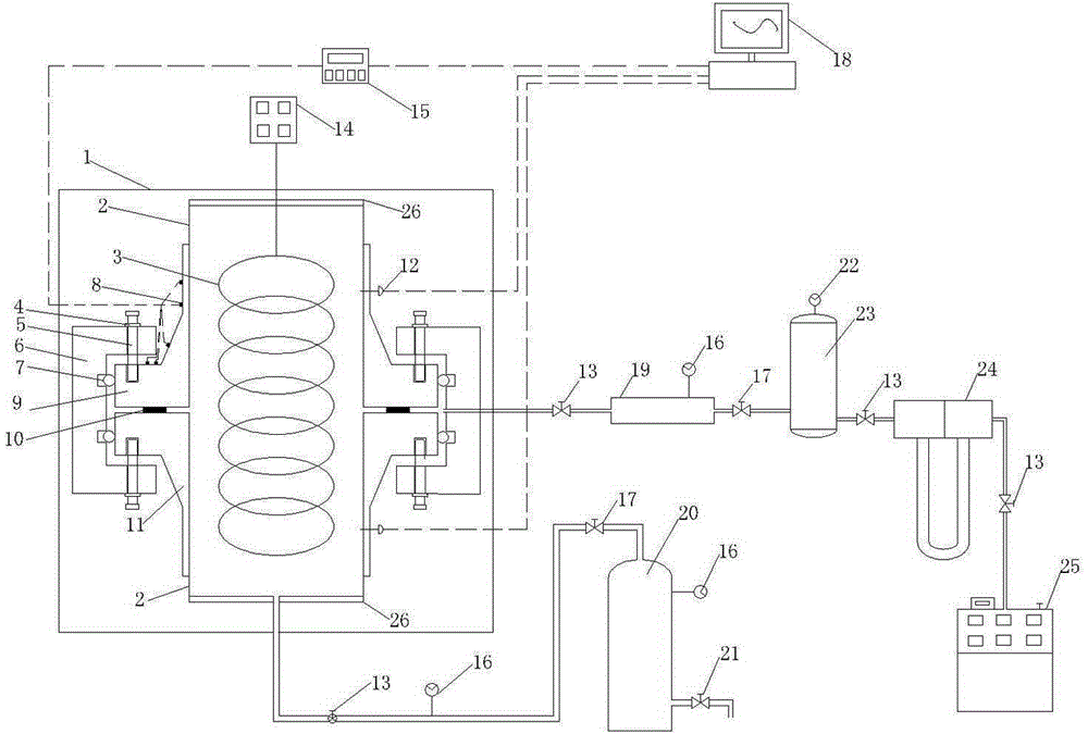
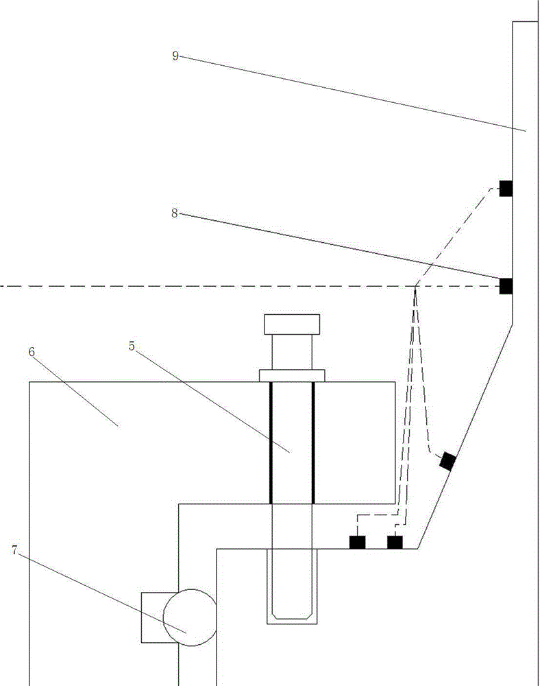
[0027] Such as figure 1 As shown, a leak detection device of a high temperature flange connection system includes two leak detection pipes 2, a first flange 9 and a second flange 11 connecting the two leak detection pipes 2, and a first flange 9 and the gasket 10 between the sealing surface of the second flange 11, the heating mechanism, the pressurizing mechanism, the non-connecting ends of the two leak detection pipes 2 are closed (through the blind plate 26) and a sealed cavity is formed inside, the heating mechanism Located in the sealed chamber, the pressurizing mechanism delivers gas to the sealed chamber; the outer side of the first flange 9 and the second flange 11 is covered with an annular rigid part 6, and the inner side of the rigid part 6 is provided with two annular grooves, and the annular concave Sealing rings 7 are provided in the groo...


PUM


Abstract

The invention relates to a leakage detecting device of a high-temperature flange connecting system. The leakage detecting device comprises a sealed cavity formed by two leakage detecting pipes, a first flange, a second flange and a gasket. A heating mechanism is arranged in the sealed cavity, and a pressurizing mechanism delivers gas into the sealed cavity. The outer side of the first flange and the outer side of the second flange are sleeved with an annular rigid piece, two annular grooves are formed in the inner side of the rigid piece and internally provided with sealing rings respectively, and the two sealing rings are in close contact with the lateral side of the first flange and the lateral side of the second flange respectively. A plurality of pairs of threaded through holes evenly distributed around the leakage detecting pipes are formed in the rigid piece, each pair of threaded through holes are symmetrical with respect to the gasket, a bolt is arranged in each threaded through hole, and the first flange and the second flange are matched and jacked through the pairs of bolts. The sealed leakage detecting cavity is defined by the gasket, the first flange, the second flange, the sealing rings and the rigid piece and connected with a mass spectrum detector through a pipe. According to the leakage detecting device, normal stressing of the gasket can not be influenced by the leakage detecting cavity, and the testing result is truer.

Description

technical field [0001] The invention relates to a leak detection device of a high temperature flange connection system. Background technique [0002] Flange connections are widely used in petroleum, chemical, aerospace and other industries. Flange connections are common connection methods in pressure vessels and pipeline equipment. Since the flange connection system works in a high temperature and high pressure working environment for a long time, for the most common bolted flanges, the flange is prone to problems such as bolt elongation, flange warping, gasket deformation, and flange deflection. Any problem will cause the bolted flange connection system to leak to a certain extent. If the system leaks, it is likely to cause economic losses and safety accidents. [0003] In order to improve the tightness of the flange connection system, it is necessary to obtain the leakage rate data of the flange connection system under high temperature and high pressure. People have desig...

Claims


Application Information

Patent Timeline
IPC IPC(8): F16L23/00
CPCF16L23/006
Inventor 郑小涛程阳喻九阳徐建民林纬潘佳琳子
Owner WUHAN INSTITUTE OF TECHNOLOGY
Why Eureka
Try Eureka