Fiber-optic gyroscope vibration signal analysis method based on improved LMD

A fiber optic gyroscope and vibration signal technology, which is applied in the field of inertial navigation and can solve the problems of large dependence of parameters such as step size, and error of smooth results.

Active Publication Date: 2016-03-23
SOUTHEAST UNIV
View PDF4 Cites 14 Cited by
  • Summary
  • Abstract
  • Description
  • Claims
  • Application Information

AI Technical Summary

Problems solved by technology

In the field of mechanical failure analysis, the application of the LMD method has achieved some innovative research results, but because the moving average algorithm adopted by the classic LMD has a large dependence on parameters such as step size, the smoothing results have obvious errors

Method used


Image

  • Fiber-optic gyroscope vibration signal analysis method based on improved LMD
  • Fiber-optic gyroscope vibration signal analysis method based on improved LMD
  • Fiber-optic gyroscope vibration signal analysis method based on improved LMD

Examples


Embodiment Construction

[0064] The present invention will be further described below in conjunction with the accompanying drawings.

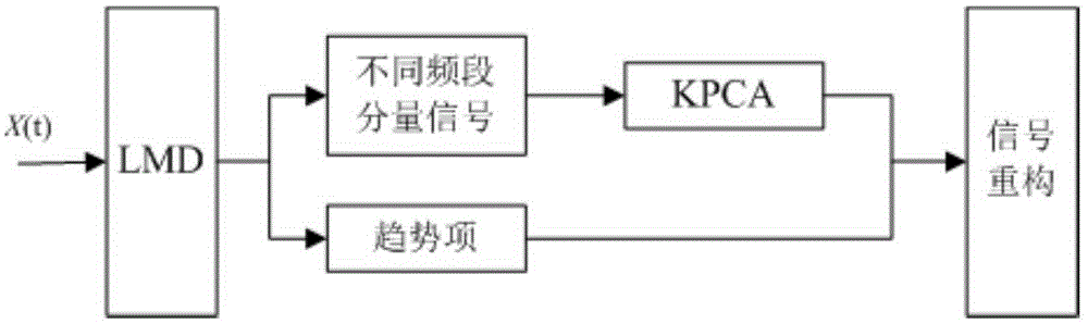
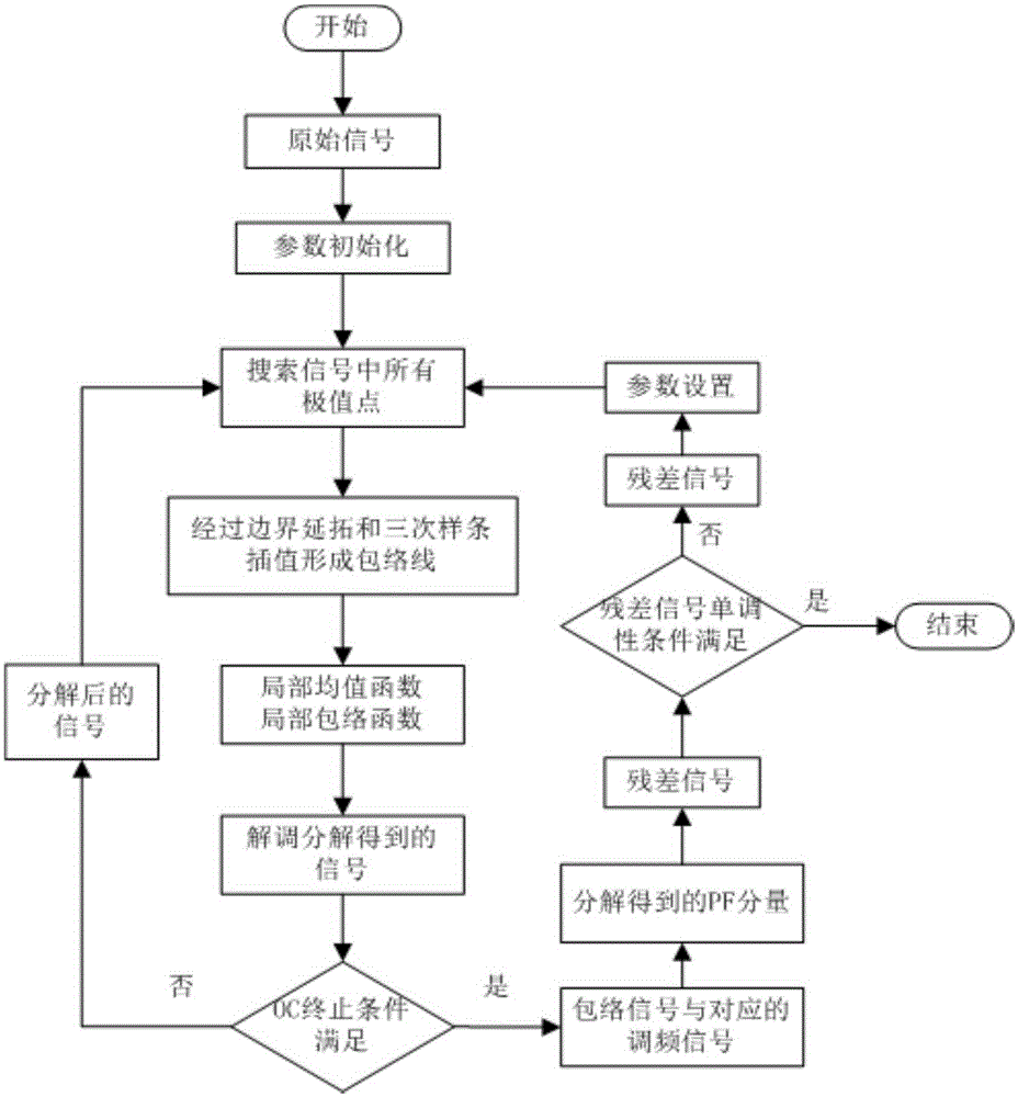
[0065] A fiber optic gyroscope vibration signal analysis method based on improved LMD, such as figure 1 , 2 As shown, the fiber optic gyroscope vibration signal is x(t), and the specific steps based on the improved LMD analysis method are as follows:

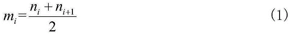
[0066] (1) Determine all extreme points n in the signal x(t) i , and calculate any two adjacent extreme points n i and n i+1 the average value of m i

[0067] m i = n i + n i + 1 2 - - - ( 21 )

[0068] Define the local magnitude a i Represents two adjacent extreme points n i an...


PUM


Abstract

The invention discloses a fiber-optic gyroscope vibration signal analysis method based on improved LMD, and belongs to the technical field of inertial navigation. The method includes the steps that time-frequency domain decomposition is performed on a vibration signal through the improved LMD method, and a series of harmonic signals corresponding to different frequency bands in the original signal are obtained; finally, construction is performed by eliminating light source fluctuation noise and gyroscopic drift caused by vibration, and an output signal with vibration noise removed is obtained. According to the improved LMD method, cubic spline interpolation is adopted for replacing a moving average method, meanwhile a mirror extension method is adopted for relieving possible end effect problems, and OC judgment with a higher convergence speed is introduced into decomposition ending conditions. A kernel principal component analysis method is used for analyzing component signals, an energy ratio method is used for separating and reflecting effective signals and noise generated under vibration influences, and finally effectiveness analysis of the fiber-optic gyroscope vibration signal is completed.

Description

technical field [0001] The invention relates to a fiber optic gyro vibration signal analysis method based on improved Local Mean Decomposition (LMD), which belongs to the technical field of inertial navigation. Background technique [0002] As an all-solid-state angular velocity measurement device widely used in inertial systems, fiber optic gyroscopes have a greater impact on the accuracy of inertial systems. Although in theory, the fiber optic gyroscope has the advantages of shock resistance and vibration resistance compared with traditional mechanical gyroscopes due to its all-solid-state and no moving parts, but due to the elastic-optical effect of optical fibers, in practical engineering applications, due to Environmental factors such as shock and vibration will cause changes in the stress of the fiber ring, and the vibration of the device pigtail and the resonance of the structure will cause gyro errors, which will increase the dynamic error of the device in the vibrat...

Claims


Application Information

Patent Timeline
Patent Type & Authority Applications(China)
IPC IPC(8): G01C25/00
CPCG01C25/005
Inventor 陈熙源宋锐崔冰波方琳
Owner SOUTHEAST UNIV
Why Eureka
Try Eureka