
Lens-free particle microscopic localization device and method based on LED light sources

A technology of LED light source and positioning device, which is used in measurement devices, particle size analysis, particle and sedimentation analysis, etc., can solve problems such as low time efficiency, particles with different axial positions easily influence each other, speckle noise limiting imaging positioning accuracy, etc. , to achieve the effect of improving recovery accuracy, simple device structure, and improving positioning accuracy

Active Publication Date: 2016-03-23
NANJING UNIV OF SCI & TECH
View PDF4 Cites 8 Cited by
  • Summary
  • Abstract
  • Description
  • Claims
  • Application Information

AI Technical Summary

Problems solved by technology

Throughout nearly half a century of progress in the field of optical measurement technology, the most classic three-dimensional structure imaging technology is tomography technology, but this technology still has its shortcomings in the application of particle localization: firstly, it is necessary to rotate the illumination or the sample to achieve a certain One layer of planar data, while the mechanical scanning device will inevitably lead to lower time efficiency, lack of real-time performance for particle positioning
Traditional holographic imaging equipment mostly uses laser light sources, and the speckle noise introduced thereby limits the improvement of its imaging positioning accuracy ([2]DaintyJC. ,9.)
At the same time, complex light source equipment will bring great inconvenience to the flexibility of the device
In the traditional holographic interferometry, because of the problem of the conjugate image, the particles located in the same plane position but with different axial positions are easy to interact with each other, so the traditional holographic interferometry must use off-axis measurement to eliminate the conjugate image ( [3] CucheE, MarquetP, DepeursingeC.Spatialfilteringforzero-orderandtwin-imageeliminationindigitaloff-axisholography[J].Appliedoptics,2000,39(23):4070-4075.)

Method used


Image

  • Lens-free particle microscopic localization device and method based on LED light sources
  • Lens-free particle microscopic localization device and method based on LED light sources
  • Lens-free particle microscopic localization device and method based on LED light sources

Examples


Embodiment Construction

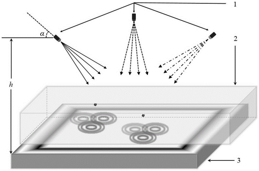
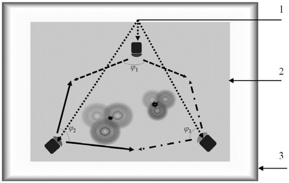
[0010] Such as figure 1 and figure 2 As shown, the lensless particle micropositioning device based on the three-color LED light source of the present invention includes an LED light source 1, a sample placement groove 2, a CMOS or CCD camera sensor 3, and more than two LED light sources 1 are arranged in the sample placement groove 2 different positions on the top to irradiate the sample at different angles; the sample placement groove 2 is set above the camera sensor 3, and the distance between the lower surface of the sample placement groove 2 and the camera sensor 3 is as small as possible, and both Keep parallel to preserve interferometric image quality.

[0011] The LED light source 1 of the lensless particle micropositioning device based on the LED light source of the present invention uses the same color or different colors. When using the same color LED, the camera sensor 3 is monochrome, and when using different color LEDs, the camera sensor 3 is color. The distanc...


PUM


Abstract

The invention discloses a lens-free particle microscopic localization device and method based on LED light sources. The lens-free particle microscopic localization device comprises the LED light sources, a sample arranging cell and a CMOS (complementary metal oxide semiconductor) or CCD (charge coupled device) camera sensor, wherein the more than two LED light sources are arranged in different positions above the sample arranging cell to irradiate a sample from different angles; the sample arranging cell is arranged above the camera sensor, the distance between the lower surface of the sample arranging cell and the camera sensor is as small as possible, and the sample arranging cell and the camera sensor keep parallel to guarantee the quality of interference images. The device is simple in structure, rapid, accurate, concise, efficient and low in cost; extraction and reduction of particle location and dimension information are realized with numerical propagation and decision methods, multi-particle information is recorded in real time, and particle tracking is realized.

Description

technical field [0001] The invention belongs to optical measurement and imaging technology, in particular to a lensless particle micro-positioning device and method based on a three-color LED light source. Background technique [0002] Particle micropositioning is an important technology for optical measurement and imaging. No matter in the field of biomedicine or detection, particle micropositioning technology is playing an important role. Throughout nearly half a century of progress in the field of optical measurement technology, the most classic three-dimensional structure imaging technology is tomography technology, but this technology still has its shortcomings in the application of particle localization: firstly, it is necessary to rotate the illumination or the sample to achieve a certain One layer of planar data, while the mechanical scanning device will inevitably lead to lower time efficiency, and lacks real-time performance for particle positioning. There is also...

Claims


Application Information

Patent Timeline
IPC IPC(8): G01N15/02
CPCG01N15/0227G01N2015/0233
Inventor 陈钱胡岩左超冯世杰顾国华张玉珍孙佳嵩张良陶天阳李加基张佳琳孔富城林飞张敏亮范瑶
Owner NANJING UNIV OF SCI & TECH
Learn More