
Hollow axle ultrasonic flaw detector

A hollow axle and ultrasonic technology, which is applied in the direction of material analysis, measuring devices, and instruments using sound waves/ultrasonic waves/infrasonic waves, can solve problems such as faster backward speed, waveform changes, and slower forward speed, and achieve wide speed changes. Improvement, accurate position and time, avoiding the effect of waveform changes

Active Publication Date: 2016-03-23
常州常瑞轨道交通科技有限公司
View PDF7 Cites 6 Cited by
  • Summary
  • Abstract
  • Description
  • Claims
  • Application Information

AI Technical Summary

Problems solved by technology

[0003] Although the weight of the flaw detection device is reduced by using wire suspension, manual operation is still required to pull the flaw detection device in a circle, move upward or move forward, and the flaw detection device itself is heavy and labor-intensive for docking. In addition, when using wire suspension for docking, it is difficult to control the docking direction of the flaw detection device, and it is easy to collide during the docking process. Experienced employees are required to operate, and they rely heavily on skilled workers
[0004] In addition, the existing hollow axle flaw detectors still have the following technical problems: 1. During ultrasonic flaw detection, the ultrasonic probe is pressed against the inner surface of the hollow axle by the probe spring for flaw detection, so that slippage occurs between the center of the inspection head and the center of the hollow axle At this time, the ultrasonic probe can only move up and down to adjust the fitting position, while the offset in other directions cannot be adjusted, so the gap between the surface of the ultrasonic probe and the inner surface of the hollow axle cannot be kept uniform, so that the supplied turbine on the surface of the ultrasonic probe The oil film will thicken, which will lead to the change of the waveform emitted and reflected by the ultrasonic generator, which will affect the accuracy of flaw detection judgment; 2. When the rotating drum is used to drive the chain forward, the number of coils of the cable drag chain on the rotating drum will gradually decrease , the forward speed of the chain will slow down, so the speed of the probe will slow down, and the walking speed of the probe will be unstable, which will affect the accuracy of flaw detection; It will become faster, and the speed of the probe rod retreating too fast will affect the flaw detection accuracy of the probe

Method used


Image

  • Hollow axle ultrasonic flaw detector
  • Hollow axle ultrasonic flaw detector
  • Hollow axle ultrasonic flaw detector

Examples


Embodiment 1

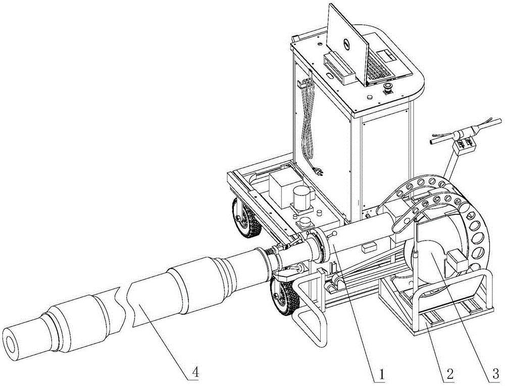
[0037] Such as Figure 1-8 As shown, the hollow axle 4 ultrasonic flaw detector of this embodiment includes a flaw detection assembly 1, a docking platform 2 and a feeding device 3. The flaw detection assembly 1 is docked with the hollow axle 4 through the docking platform 2, and is driven by the feeding device 3 into the hollow axle. 4 for testing.

[0038] Flaw detection components:

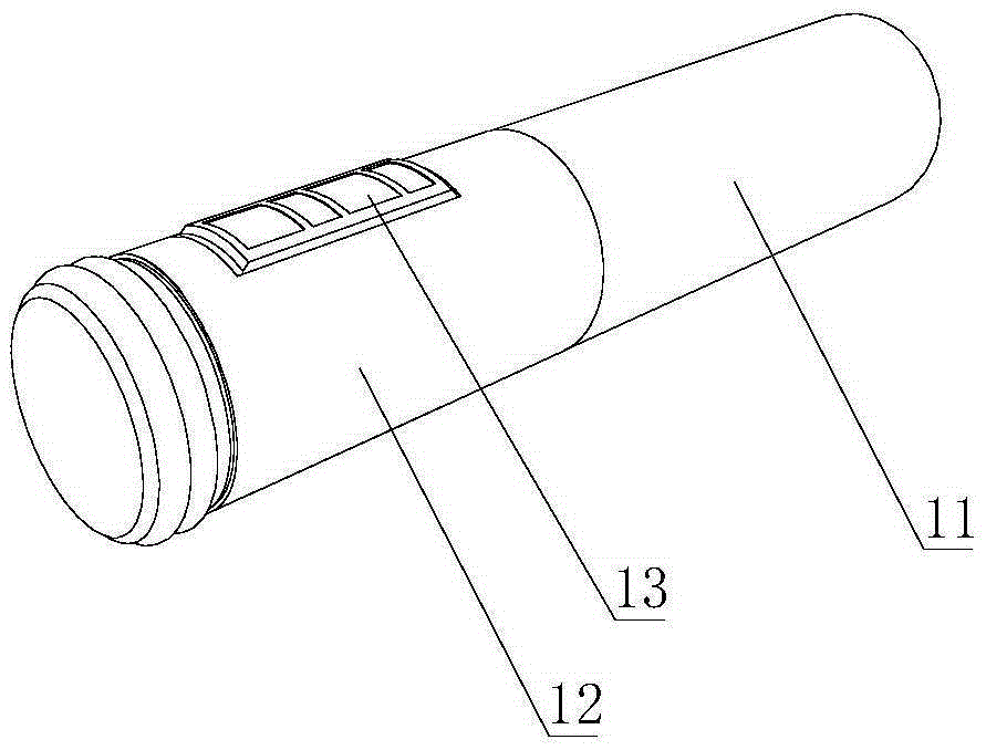
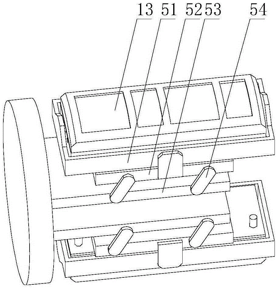
[0039] The flaw detection assembly 1 in this embodiment includes a probe rod 11, a probe rod rotating body 12 rotatably installed on the probe rod 11, and an ultrasonic probe 13 installed on the probe rod rotating body 12. In order to prevent the surface of the ultrasonic probe 13 from being The oil film of the supplied turbine oil is thickened, avoiding the change of the waveform emitted and reflected by the ultrasonic generator, and ensuring that the position and time of the ultrasonic probe 13 transmitting and receiving ultrasonic waves are accurate during detection. The ultrasonic probe 13...


PUM


Abstract

The invention relates to the technical field of ultrasonic flaw detection, in particular to a hollow axle ultrasonic flaw detector, which includes a flaw detection assembly, a docking platform and a feeding device. The flaw detection assembly is in butt joint with a hollow axle through the docking platform, and is driven by the feeding device to enter the hollow axle to perform detection. The hollow axle ultrasonic flaw detector no longer uses a line type balancer while installing the flaw detection assembly to the axle, but uses the docking platform to bear the flaw detection assembly, thus alleviating the labor force needed for left-right movement and up-down movement of the flaw detection assembly. In addition, an ultrasonic probe adjusts the gap between the outer surface of the ultrasonic probe and the inner surface of the hollow axle through a self-adaptive adjustment device, so that the gap between the ultrasonic probe surface and the hollow axle inner surface can always keep consistent during high-speed rotating flaw detection by the universal probe, thus preventing a supplied turbine oil membrane on the ultrasonic probe surface from thickening, and ensuring accurate time and locations for ultrasonic wave emission and ultrasonic wave receiving during ultrasonic probe detection.

Description

technical field [0001] The invention relates to the technical field of ultrasonic flaw detection, in particular to a flaw detection device for hollow axle flaw detection. Background technique [0002] When testing the hollow axle, it is necessary to insert a flaw detection head into the hollow structure of the hollow axle, and then rotate the flaw detection head to advance and detect flaws, for example, No. "20720034793.0", a utility model patent publication named "Hollow Axle Ultrasonic Flaw Detector" A hollow axle ultrasonic flaw detection machine is provided, the machine body is provided with a lifting mechanism seat and a rotating mechanism seat, and the feeding mechanism seat is installed on the lifting mechanism seat through the rotating mechanism seat. The lifting mechanism mount can be raised and lowered by a motor-driven lead screw, and the aforementioned lifting mechanism mount and rotating mechanism mount can facilitate the staff to insert the probe rod into the h...

Claims


Application Information

Patent Timeline
Patent Type & Authority Applications(China)
IPC IPC(8): G01N29/265
CPCG01N29/265
Inventor 肖潇彭政峰潘振新
Owner 常州常瑞轨道交通科技有限公司
Learn More