
An air-conditioning pipeline velocity monitor

A technology for air-conditioning pipes and monitors, which is applied in fluid velocity measurement, velocity/acceleration/impact measurement, instruments, etc. It can solve the problems of high cost of mechanical flowmeter, large flow resistance of impeller flowmeter, and high requirements for the use of rings. Achieve the effects of good fixing effect, low wind resistance and high clamping force

Active Publication Date: 2018-09-21
NANTONG GUOMIQI MASCH EQUIP CO LTD
View PDF14 Cites 0 Cited by
  • Summary
  • Abstract
  • Description
  • Claims
  • Application Information

AI Technical Summary

Problems solved by technology

[0007] The technical problem to be solved by the present invention is: to overcome the technical problems in the prior art, such as the high cost of the mechanical flow meter, the high requirements for the use of the ring, the large flow resistance of the impeller type flow meter, and the difficulty in installation, etc., to provide a flow rate monitor for air-conditioning pipelines

Method used


Image

  • An air-conditioning pipeline velocity monitor
  • An air-conditioning pipeline velocity monitor

Examples


Embodiment Construction

[0026] The present invention is described in further detail now in conjunction with accompanying drawing. These drawings are all simplified schematic diagrams, which only illustrate the basic structure of the present invention in a schematic manner, so they only show the configurations related to the present invention.

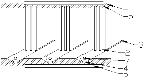
[0027] Such as figure 1 As shown, the present invention is a flow rate monitor for air-conditioning ducts. The monitor includes a beam tube 1 installed on the inner wall of the air-conditioning duct, and several windward plates 2 are arrayed in the beam tube 1; windward One axial end of the plate 2 is rotationally connected with the inner wall of the beam tube 1, a fixed surface is provided on the freely rotating end of the windward plate 2, and a number of resistance strain gauges are arranged in a linear array between the fixed surface and the inner wall of the beam tube 1. The surface of the resistance strain gauge 5 is parallel to the axis of the beam tub...


PUM


Abstract

The invention relates to an air conditioner pipeline flow velocity monitor. The monitor comprises a beam pipe installed on an inner wall of an air conditioner air duct. Several windward plates are arranged in the beam pipe in an array mode. One axial end of each windward plate is rotatably connected to an inner wall of the beam pipe. A free rotation end portion of each windward plate is provided with one fixing plane. Several resistance strain gauges are arranged between the fixing plane and the inner wall of the beam pipe in a linear array mode. Surfaces of the resistance strain gauges are parallel to an axis of the beam pipe. One windward sheet is fixed to the free rotation end of each windward plate. The surface of the windward sheet is inclined relative to the axis of the beam pipe. When the windward sheet bears wind pressure, the resistance strain gauges are tensioned by the windward plates, the windward plates and the windward sheet are coplanar, and the surface of the windward sheet is inclined relative to the axis of the beam pipe.

Description

technical field [0001] The invention relates to a flow rate monitor of an air-conditioning pipeline, which belongs to the field of fluid monitoring equipment. Background technique [0002] In the use of large-scale air temperature control and circulation equipment, it is included in the central duct air conditioner, and more air ducts are often used for air guidance. At the same time, in order to achieve air filtration and heat exchange, the air duct In order to monitor the normal operation of various equipment and components, various types of flow rate monitors will be installed in the pipeline. While monitoring the flow rate of the pipeline, it can realize Automatic control of drainage fans, heat exchangers and other equipment in the pipeline; [0003] The traditional gas flow meter is generally an anemometer. Its basic principle is to place a thin metal wire in the fluid, and heat the wire through an electric current to make its temperature higher than the temperature of...

Claims


Application Information

Patent Timeline
Patent Type & Authority Patents(China)
IPC IPC(8): G01P5/07
CPCG01P5/07
Inventor 薛晓刚陈华张彬卫
Owner NANTONG GUOMIQI MASCH EQUIP CO LTD
Learn More