Method for assembling fuel cell stack

A fuel cell stack and assembly method technology, applied in the direction of fuel cell grouping, fuel cells, circuits, etc., can solve the problems of single cell offset, poor contact, distortion and deformation of ultra-thin flow field plates, etc., to achieve dimensional stability, The effect of simple design and strong practicability

Active Publication Date: 2016-03-23
武汉理工新能源有限公司
View PDF4 Cites 13 Cited by
  • Summary
  • Abstract
  • Description
  • Claims
  • Application Information

AI Technical Summary

Problems solved by technology

This method has two deficiencies: on the one hand, the positioning column is not effectively fixed, and the column is prone to deformation during extrusion. If the number of cells is large, the components of the stack will squeeze the column, and the column will be damaged due to the lack of effective external fixation of the column. Deformation can easily cause offset between single cells, and it is impossible to ensure accurate positioning and stacking
As the number of single cells increases, this effect will be more serious; on the other hand, if the flow field plate is long, the middle side will not be positioned, which will easily cause distortion and deformation of the ultra-thin flow field plate. This method only uses columns to limit the four corners. Especially for the commonly used metal plates (size: length 300mm, width 10mm, thickness 0.1mm), when being squeezed, it is easy to cause the middle part of the ultra-thin metal plate to be distorted and deformed, and the components cannot be aligned, resulting in contact Not good, poor sealing, air leakage, directly affect the performance of the stack

Method used


Image

  • Method for assembling fuel cell stack
  • Method for assembling fuel cell stack
  • Method for assembling fuel cell stack

Examples


Embodiment Construction

[0031] The content of the present invention is illustrated below in conjunction with the accompanying drawings and embodiments.

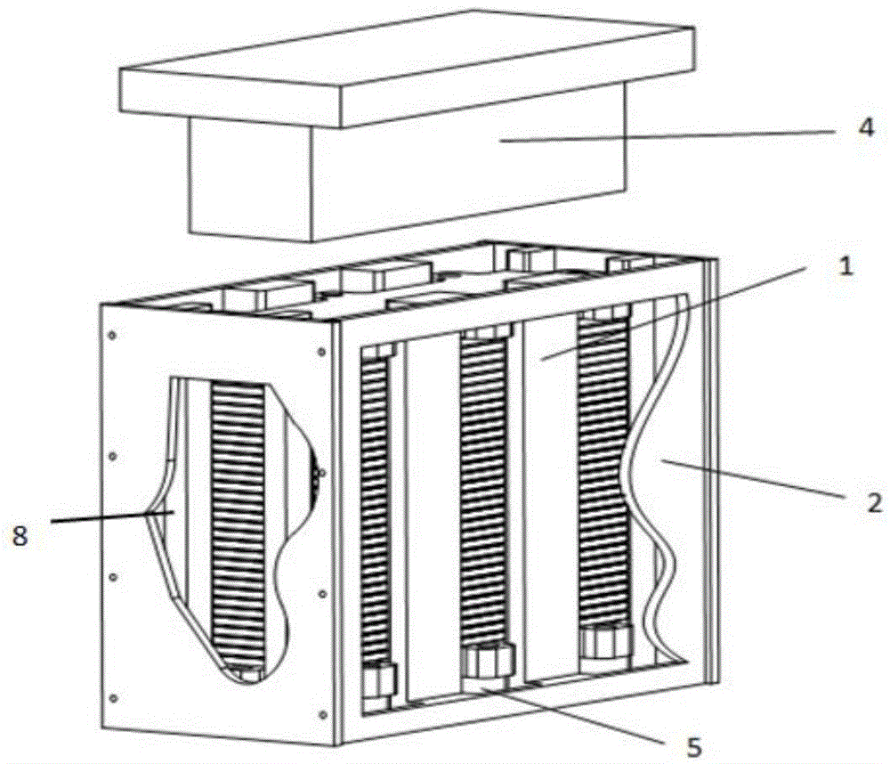
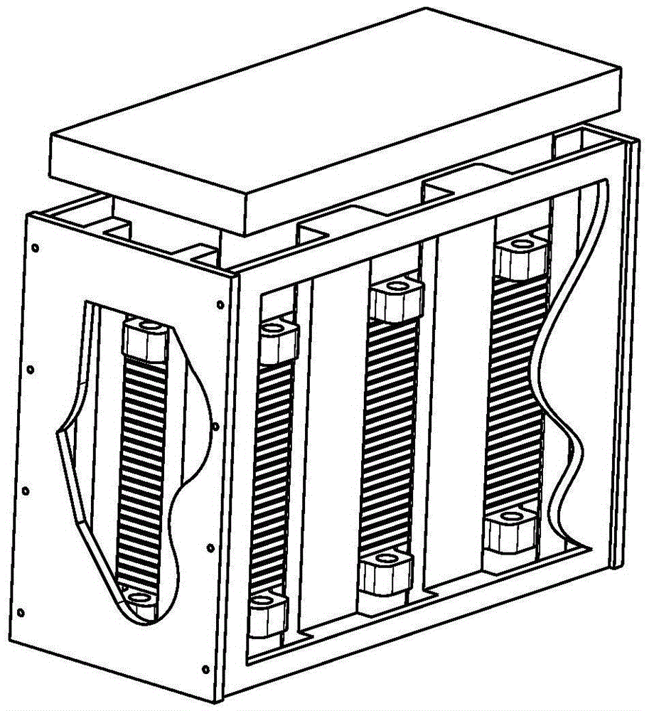
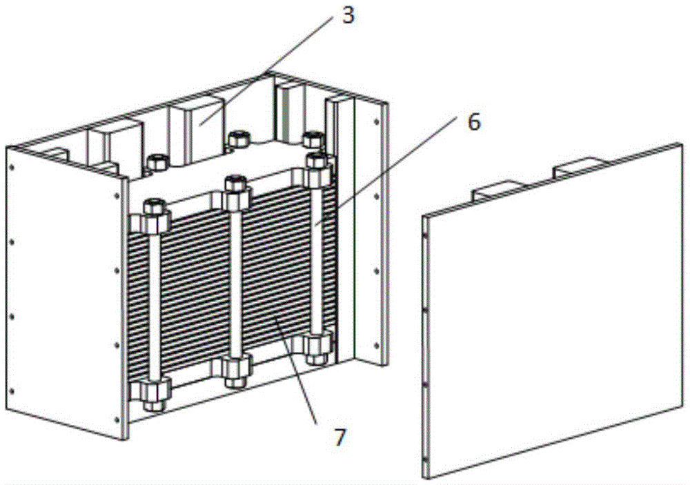
[0032] Such as Figure 1 to Figure 4 As shown, the embodiment of the present invention provides an assembly device for a fuel cell stack, which includes a fixing mechanism, a positioning mechanism, a pressure supply device and a locking mechanism.

[0033] In this embodiment, the fixing mechanism is the fixing frame 2 . The positioning mechanism includes multiple sets of positioning columns, each group of positioning columns includes at least two positioning columns 1, and each group of positioning columns is respectively fixed on the inner surface of each side plate of the fixed frame 2, which can be fixed by means of screws. Each positioning column 1 includes a first surface 8 and a second surface 3 parallel to each other, and the first surface 8 of each positioning column 1 is in contact with the inner surface of the side plate of the fixing fra...


PUM


Abstract

The invention relates to a method for assembling a fuel cell stack. The method comprises a step (1) of providing a fixing mechanism, a location mechanism, a pressure supply mechanism and a locking mechanism; a step (2) of successively placing a lower end plate, a current collecting plate, an assembly stack single cell, a current collecting plate and an upper end plate of the stack into the fixing mechanism in sequence, wherein each location post of the fixing mechanism is perpendicular to the stack to enable the periphery of the stack to be nested in a space defined by a second surface of each location post; a step (3) of utilizingpressure blocks of the pressure supply device to exert pressure in the direction perpendicular to the stack on the upper end plate and the lower end plate of stack parts to compress each part of the stack to meet set requirements; a step (4) of utilizing the locking mechanism to fix each part of the stack to achieve the purpose of assembling the stack; and a step (5) of removing the pressure, removing the fixing mechanism and the location mechanism and taking down the stack to finish the assembly of the stack. The method for locating and assembling the assembly stack is simple and convenient to operate, high in actionability and precise in location. The location mechanism ensures that all parts of the stack are in contact uniformly without deviation. The pressure blocks of the pressure supply device ensure each assembly of the assembly stack to be forced uniformly, and the quality of the assembly stack is guaranteed.

Description

technical field [0001] The invention relates to the technical field of fuel cells, in particular to an assembly method of a fuel cell stack. Background technique [0002] A fuel cell is a device that directly uses hydrogen to generate electricity. The chemical energy of hydrogen and oxygen is directly converted into electrical energy. Since it does not go through the Carnot cycle, the energy conversion rate is high; the product is only water, and the fuel cell is more environmentally friendly. Hydrogen energy is also known as the ultimate environmentally friendly energy, while fuel cell technology is considered to be the preferred energy-saving, efficient and environmentally friendly power generation technology in the 21st century. [0003] The reaction principle of the proton exchange membrane fuel cell is as follows: [0004] Anode: H 2 →2H + +2e - [0005] Cathode: O 2 +2H + +2e - →H 2 O; [0006] The electrons generated by the anode can only reach the cathode t...

Claims


Application Information

Patent Timeline
Patent Type & Authority Applications(China)
IPC IPC(8): H01M8/2404
CPCH01M8/24Y02E60/50
Inventor 潘牧宛朝辉廖鑫范卫东王顺忠
Owner 武汉理工新能源有限公司
Why Eureka
Try Eureka