Fuel injection valve

A fuel injection valve and valve core technology, which is applied to fuel injection devices, special fuel injection devices, charging systems, etc., can solve problems such as prolonged time, and achieve the effects of preventing sticking, fast response, and small deviation

Inactive Publication Date: 2016-03-23
HITACHI AUTOMOTIVE SYST LTD
View PDF3 Cites 3 Cited by
  • Summary
  • Abstract
  • Description
  • Claims
  • Application Information

AI Technical Summary

Problems solved by technology

[0010] Moreover, in the existing fuel injection valve, there is such a problem that after the spool has fully reached the valve opening position, the collision surface between the end surface of the armature and the end surface of the fixed core sticks to each other, even in order to make the spool After returning to the closed position to stop energizing the electromagnetic coil and disappearing the magnetic force of the magnetic circuit, it takes longer for the armature to return to the initial position, that is, the state where the two are completely separated and the valve core is pressed to the valve seat.

Method used


Image

  • Fuel injection valve
  • Fuel injection valve
  • Fuel injection valve

Examples


Embodiment Construction

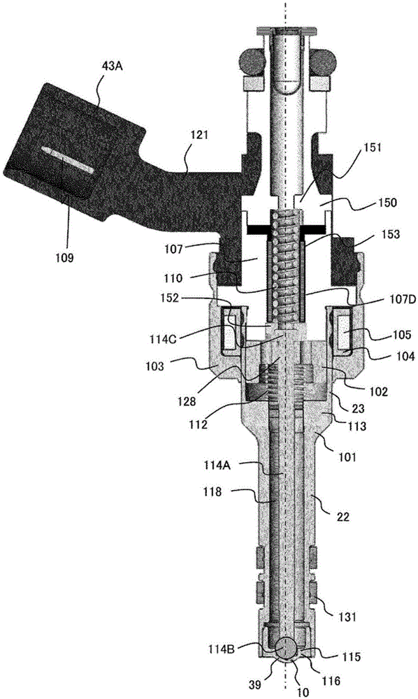
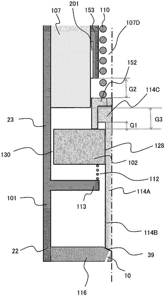
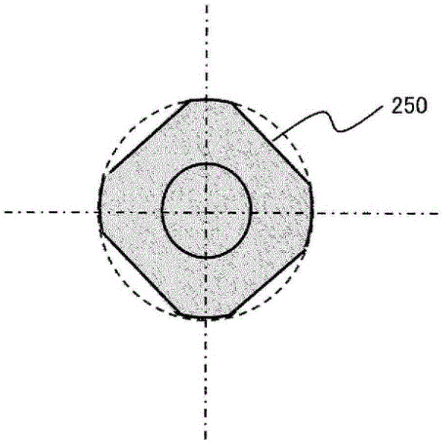
[0038] Use the following Figure 1-7 The figure illustrates the construction of an embodiment of the fuel injection valve of the present invention. figure 1 It is a longitudinal sectional view of the fuel injection valve of this embodiment. Figures 2, 4, and 6 are figure 1A partially enlarged view of , showing the details of the fuel injection valve in this embodiment. In this figure, the dimensions of parts and gaps are exaggerated compared to the actual scale to make the structure easier to understand, and unnecessary parts are omitted to explain the functions.

[0039] The nozzle holder 101 includes a small-diameter cylindrical portion 22 with a small diameter and a large-diameter cylindrical portion 23 with a large diameter. The fixed core 107 is press-fitted into the inner peripheral portion of the large-diameter cylindrical portion 23 of the nozzle holder 101, and welded at the press-fit contact position. This welded joint seals the gap formed between the inside of t...


PUM


Abstract

To improve precision in the injection amount of a fuel injection valve, the opening and closing action of a valve body must be performed quickly. In a structure in which the fluid force produced in a seat of a valve body is not transmitted immediately after a needle begins to move, adhesion between an end surface of an anchor and an end surface of a stationary core must be impeded and these end surfaces must be prevented from sticking together. To solve this problem, the present invention is a structure in which a valve body of an electromagnetic fuel injection valve comprises a second valve body in contact with the anchor when the valve is closed, and a first valve body in contact with the anchor while the valve is opening. The second valve body comes in contact with a stroke stopper disposed on the inner periphery of the stationary core when the valve opens, the lengths of the first valve body and the second valve body are stipulated so that the stationary core and the anchor do not come into direct contact and a gap is ensured when the valve opens, and the process of plating the stationary core and the anchor is discontinued.

Description

technical field [0001] The present invention relates to a fuel injection valve used in an internal combustion engine, in particular to a valve that uses an electromagnetically driven movable element to open and close a fuel passage. Background technique [0002] An internal combustion engine is equipped with a fuel injection control device that performs calculations for converting an appropriate fuel amount according to an operating state into an injection timing of a fuel injection valve, and drives a fuel injection valve that supplies fuel. The fuel injection valve uses the magnetic force generated by the current flowing into the internal solenoid to operate the movable element constituting the fuel injection valve to open and close the spool to inject fuel. The amount of injected fuel is mainly determined by the pressure difference between the fuel pressure and the pressure of the atmosphere at the nozzle port of the fuel injection valve, and the time during which the fue...

Claims


Application Information

Patent Timeline
Patent Type & Authority Applications(China)
IPC IPC(8): F02M51/06
CPCF02M51/0671F02M63/0022F02M51/066F02M2200/50F02M63/0075F02M51/061
Inventor 三宅威生宫本明靖安部元幸小仓清隆饭塚贵敏
Owner HITACHI AUTOMOTIVE SYST LTD
Why Eureka
Try Eureka