Flow pipeline for fire engine

A flow pipe and fire truck technology, applied in fire rescue and other directions, can solve the problems of intermittent, discontinuous foam, affecting the fire extinguishing effect, etc., and achieve good foaming effect.

Active Publication Date: 2016-03-30
GUANGDONG YONGQIANG ALB INT FIRE FIGHTING ENGINE
View PDF9 Cites 0 Cited by
  • Summary
  • Abstract
  • Description
  • Claims
  • Application Information

AI Technical Summary

Problems solved by technology

Because the existing flow pipeline cannot control the flow ratio of water and foam in the foam mixture or the air-foam mixture flowing through it in real time, the foaming effect of the foam mixture is not good, and foam often occurs during fire extinguishing Intermittent and discontinuous pheno

Method used


Image

  • Flow pipeline for fire engine
  • Flow pipeline for fire engine

Examples


Embodiment 1

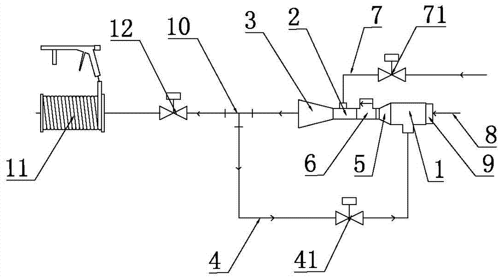
[0044] One of the specific implementations of a flow pipeline for a fire truck of the present invention, such as figure 1 As shown (the direction of the arrow in the figure is the flow direction of the liquid flow in the pipeline), its structure includes a suction pipe 1, a throat pipe 2 and a diffuser pipe 3 connected in sequence according to the flow direction of the liquid flow. The first water inlet of the suction pipe 1 passes through the high pressure The water pipe 8 is connected to the water pump, the second water inlet of the suction pipe 1 is connected to the water outlet of the diffuser pipe 3 through the return pipe 4, the return pipe 4 is provided with a return control valve 41, and a horn-shaped The throat inlet pipe 5, the large port of the throat inlet pipe 5 is connected to the suction pipe 1, the small port of the throat inlet pipe 5 is connected to the throat pipe 2, and the end of the throat pipe 2 near the diffuser pipe 3 is connected with a foam pipe 7, an...

Embodiment 2

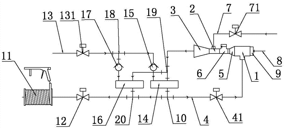
[0051] The second specific embodiment of a flow pipeline for a fire truck of the present invention is as follows: figure 2As shown (the direction of the arrow in the figure is the flow direction of the liquid flow in the pipeline), the main technical solution of this embodiment is the same as that of Embodiment 1, and the features not explained in this embodiment are explained in Embodiment 1, here No further details will be given. The difference between this embodiment and Embodiment 1 is that an air pipe 13 for conveying compressed air is also connected to the water outlet of the diffuser pipe 3, and a first proportional control valve 14 is provided at the connection between the air pipe 13 and the diffuser pipe 3, and then The flow value of the foam mixture and the flow value of the compressed air can be regulated continuously and in a certain proportion. The air pipe 13 is also provided with a first one-way valve 15 to prevent the compressed air from flowing backward. Th...


PUM


Abstract

The invention discloses a flow pipeline for a fire engine, and relates to the technical field of the fire engine. The structure of the flow pipeline comprises a suction pipe, a throat pipe and a diffusion pipe which are sequentially connected in a liquid flowing direction, wherein a water outlet of the diffusion pipe is connected with a second water inlet of the suction pipe through a reflowing pipe, besides, a flow meter is arranged at the end part, near the suction pipe, of the throat pipe, partial foam mixed liquor flowing out of the water outlet of the diffusion pipe reflows into the suction pipe through the reflowing pipe, in this way, under the condition that the pressure of a water pump does not need to be increased, the flow value of the foam mixed liquor flowing into the suction pipe can be increased, and further the flow value of the whole flow pipeline is increased; besides, according to real-time monitoring of the flow meter on the flow value, the flow value of foam entering into the throat pipe can be adjusted in a real-time manner, further the mixing ratio of water to the foam is adjusted and controlled, the foaming effect is good, and the situation that the foam generated during a fire is extinguished has continuity and stability is guaranteed.

Description

technical field [0001] The invention relates to the technical field of fire trucks, in particular to a flow pipeline for fire trucks. Background technique [0002] The flow pipeline of the fire truck is generally used to connect the fire pump and the fire extinguishing spray device. The fire pump delivers the pressurized water to the fire extinguishing spray device through the flow pipeline. Extinguish fire at source. [0003] For different types of fire sources, the fire extinguishing agent of the fire truck includes not only water, but also a foam mixture of water and foam. In order to achieve the best fire extinguishing effect, it even includes compressed air, water and foam mixed in a certain proportion. into the air-foam mixture. Because the existing flow pipeline cannot control the flow ratio of water and foam in the foam mixture or the air-foam mixture flowing through it in real time, the foaming effect of the foam mixture is not good, and foam often occurs during f...

Claims


Application Information

Patent Timeline
IPC IPC(8): A62C31/00A62C27/00
CPCA62C27/00A62C31/00
Inventor 陈平添
Owner GUANGDONG YONGQIANG ALB INT FIRE FIGHTING ENGINE
Why Eureka
Try Eureka