Spray painting machine

A spraying machine and rack technology, applied in the direction of spraying devices, etc., can solve the problems of difficulty in achieving uniform coverage of sprayed coatings on workpieces, complicated control of power devices, and increased spraying time, so as to meet the needs of mass production and improve product cleanliness , Improve the effect of product surface quality

Inactive Publication Date: 2016-03-30
SHENZHEN MATSUZAKL ROBOT AUTOMATION EQUIP CO LTD
View PDF11 Cites 34 Cited by
  • Summary
  • Abstract
  • Description
  • Claims
  • Application Information

AI Technical Summary

Problems solved by technology

[0002] Most of the traditional reciprocating spraying machines provide three-axis spraying directions of X, Y, and Z, and the spray gun cannot rotate. This will cause uneven paint spraying when spraying arc-shaped workpieces, and it is difficult to achieve uniform coverage of the sprayed layer on the workpiece. , affecting the spraying quality
Therefore, in order to improve the spraying quality, when spraying a cylindrical workpiece with a small size, it is usually necessary for the station for pos

Method used


Image

  • Spray painting machine
  • Spray painting machine
  • Spray painting machine

Examples


Embodiment Construction

[0027] The present invention will be further described below in conjunction with the accompanying drawings and specific embodiments. Terms such as "upper", "lower", "left", "right", "middle" and "one" quoted in all embodiments are only for convenience of description, and are not intended to limit the implementation of the present invention Changes or adjustments in their relative relationships, without substantial changes in technical content, should also be regarded as the scope of implementation of the present invention.

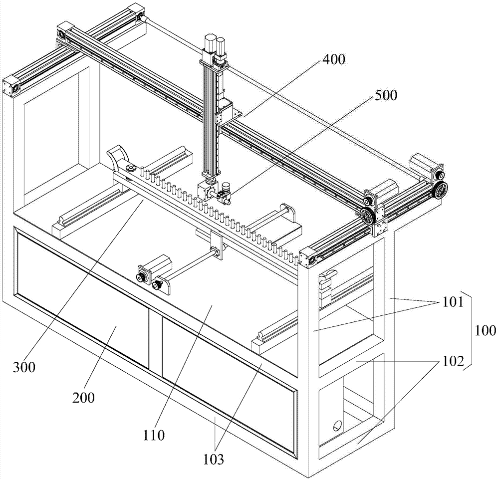
[0028] See figure 1 , a spraying machine designed in a preferred embodiment of the present invention, which includes: frame 100, horizontal electric box 200, synchronous turntable 300 and five-axis mechanism 400, horizontal electric box 200, synchronous turntable 300 and five-axis mechanism 400 They are arranged on the rack 100 sequentially from bottom to top.

[0029] Specifically, the frame 100 includes two left and right unilateral frames opposite to ...


PUM


Abstract

The invention discloses a spray painting machine. The spray painting machine comprises a spray gun, a machine frame, a control console arranged on the machine frame, and a horizontal electric box located below the control console. The spray painting machine further comprises a synchronous rotary table and a five-axis mechanism, wherein the synchronous rotary table is arranged on the control console, and a plurality of workpieces can be mounted on the synchronous rotary table at the same time; the five-axis mechanism is mounted at the top end of the machine frame and drives the spray gun. The five-axis mechanism comprises a Z-axis linear sliding table driving the spray gun to move up and down, an X-axis linear sliding table driving the Z-axis linear sliding table to move left and right, a Y-axis linear sliding table driving the X-axis linear sliding table to move front and back, a W-axis rotating mechanism and a P-axis rotating mechanism, wherein the W-axis rotating mechanism and the P-axis rotating mechanism are mounted on the Z-axis linear sliding table and drive the spray gun to rotate. According to the spray painting machine, the Z-axis linear sliding table and the station rotary table are innovated and improved, so that the spray gun has the two-direction rotating function, all the workpieces have the consistent rotating angle, the automation degree is improved, product surface quality and product consistency are improved, and synchronous rotating spray painting of the multiple workpieces is achieved.

Description

technical field [0001] The invention relates to the field of spraying machines, in particular to a five-axis reciprocating spraying machine. Background technique [0002] Most of the traditional reciprocating spraying machines provide three-axis spraying directions of X, Y, and Z, and the spray gun cannot rotate. In this way, when spraying arc-shaped workpieces, the paint will be sprayed unevenly, and it is difficult to achieve uniform coverage of the sprayed layer on the workpiece. , affect the spraying quality. Therefore, in order to improve the spraying quality, when spraying a cylindrical workpiece with a small size, it is usually necessary for the station for positioning the workpiece to be able to rotate automatically. However, the rotary station turntables in the prior art are all relatively independent rotations, and often can only be rotated at one time. Spraying 1~2 pieces, the degree of mass production is low, the production efficiency is not high, and the contro...

Claims


Application Information

Patent Timeline
IPC IPC(8): B05B13/02B05B15/08B05B15/68
CPCB05B13/02B05B13/0228B05B15/68
Inventor 韩松山
Owner SHENZHEN MATSUZAKL ROBOT AUTOMATION EQUIP CO LTD
Why Eureka
Try Eureka