Centrifugal fluid pump apparatus

a centrifugal pump and fluid pump technology, which is applied in the direction of piston pumps, positive displacement liquid engines, prostheses, etc., can solve the problems of inability to maintain the function of the centrifugal pump by rotating the impeller, troublesome control systems, and inability to achieve proper control

Inactive Publication Date: 2005-01-11
TC1 LLC
View PDF8 Cites 23 Cited by
  • Summary
  • Abstract
  • Description
  • Claims
  • Application Information

AI Technical Summary

Benefits of technology

The centrifugal fluid pump apparatus comprises a pump body in which an impeller rotates without contacting a housing; and a control mechanism for said pump body, said pump body including: said housing having a blood inlet port and a blood outlet port; a centrifugal pump section including an impeller having a first magnetic material and a second magnetic material and rotating in said housing to feed a fluid by a centrifugal force generated during its rotation; an impeller rotational torque generation section including a rotor having a magnet for attracting said first magnetic material of said impeller and a motor for rotating said rotor; an impeller position control section having an electromagnet for attracting said second magnetic material of said impeller; a position sensor for detecting a position of said impeller; and a groove for hydrodynamic bearing provided on an inner surface of said housing at a side of said rotor or on a surface of said impeller at a side of said rotor, said control mechanism comprising: a position sensor output monitoring function or an electromagnet current monitoring function; a motor current monitoring function; a failure detection function fo...

Problems solved by technology

In the case where a trouble occurs in the control system of the magnetic bearing of the conventional centrifugal pump, it is impossible to maintain the function of the centrifugal pump by rotating the impeller.
Thus if devices constituting the control sy...

Method used


Image

  • Centrifugal fluid pump apparatus
  • Centrifugal fluid pump apparatus
  • Centrifugal fluid pump apparatus

Examples


Embodiment Construction

An embodiment of the centrifugal fluid pump apparatus according to the present invention is described below with reference to drawings.

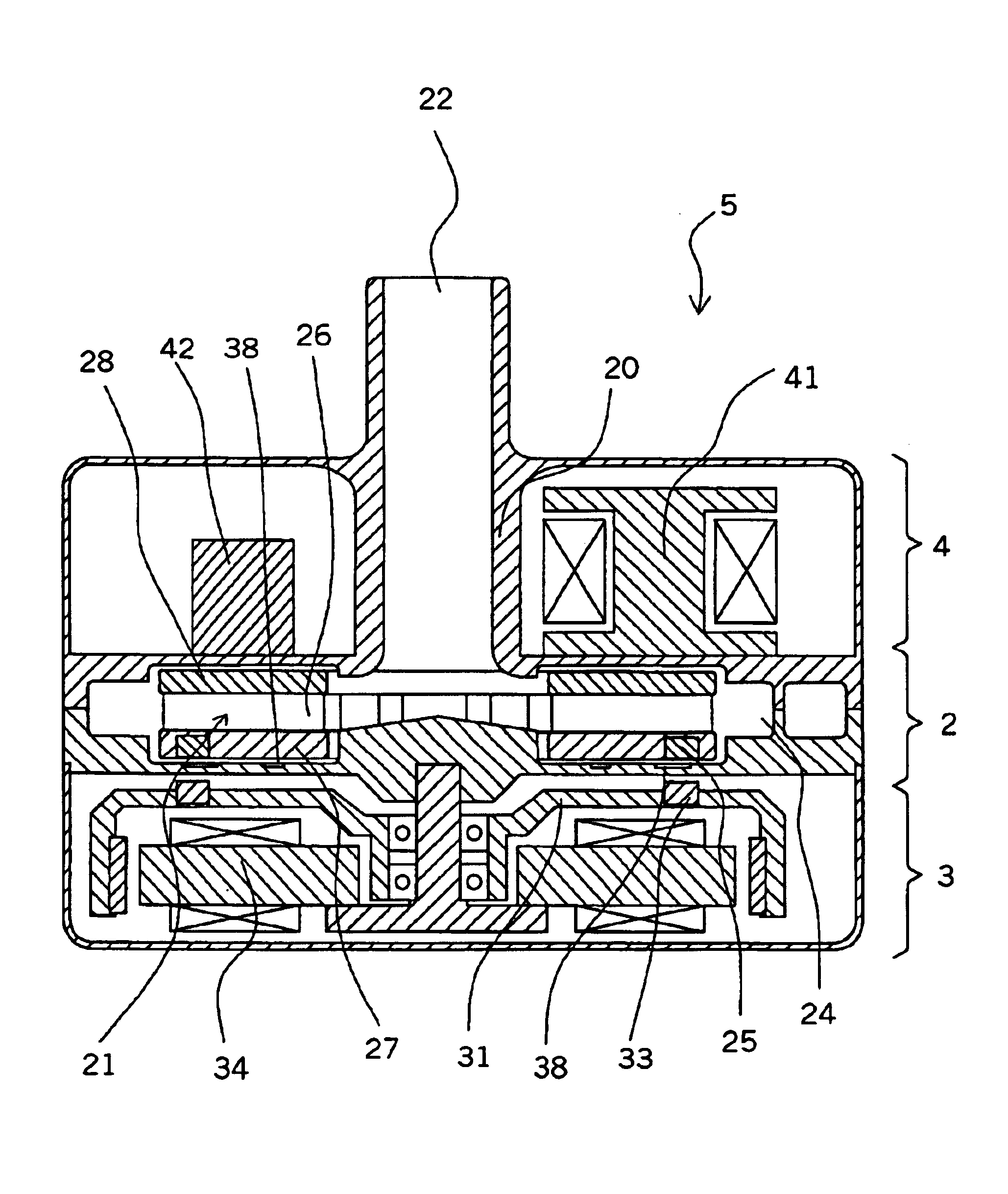
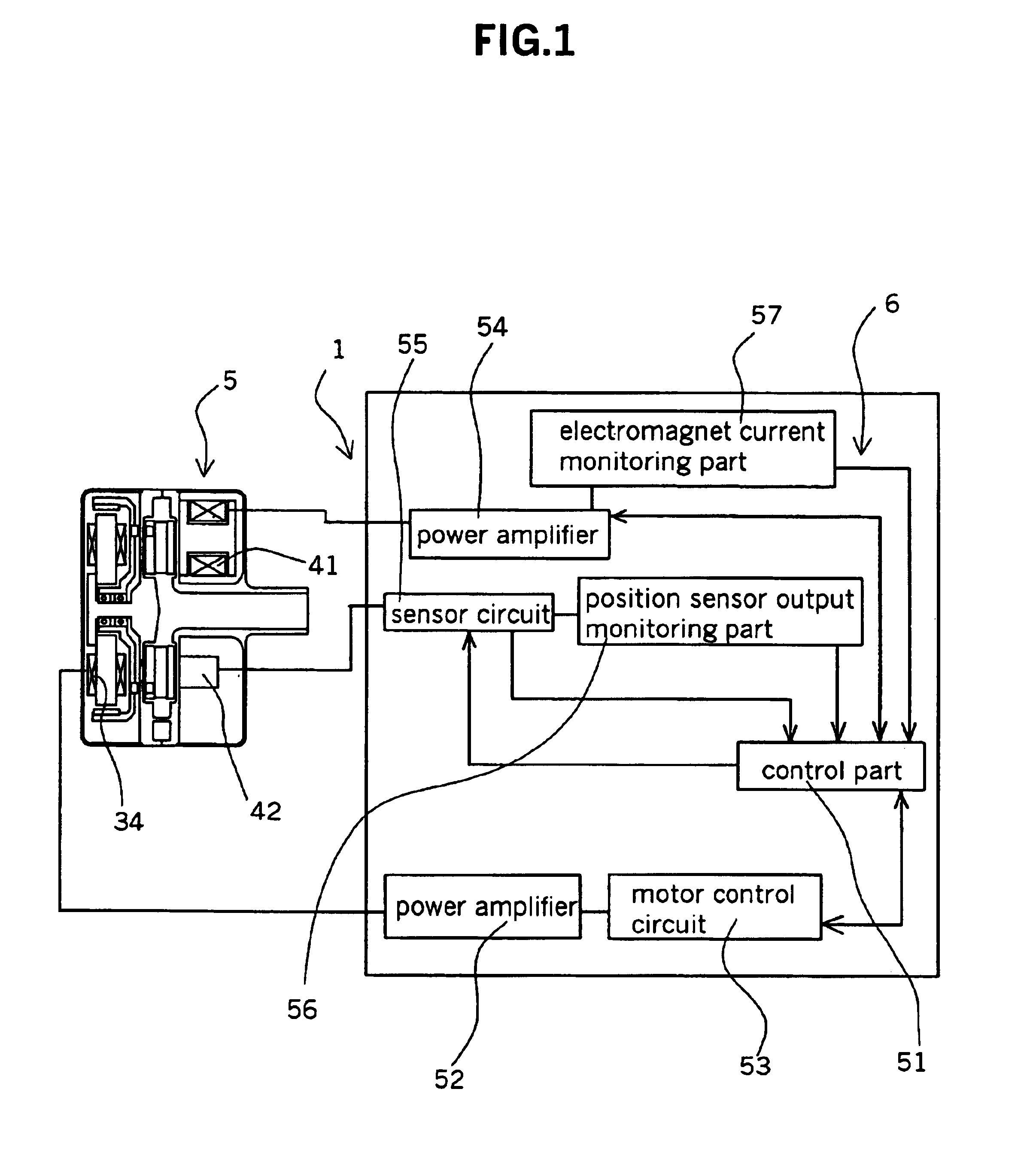
A centrifugal fluid pump apparatus 1 of the present invention includes a pump body 5 in which an impeller 21 rotates without contacting a housing 20; and a control mechanism 6 for the body 5.

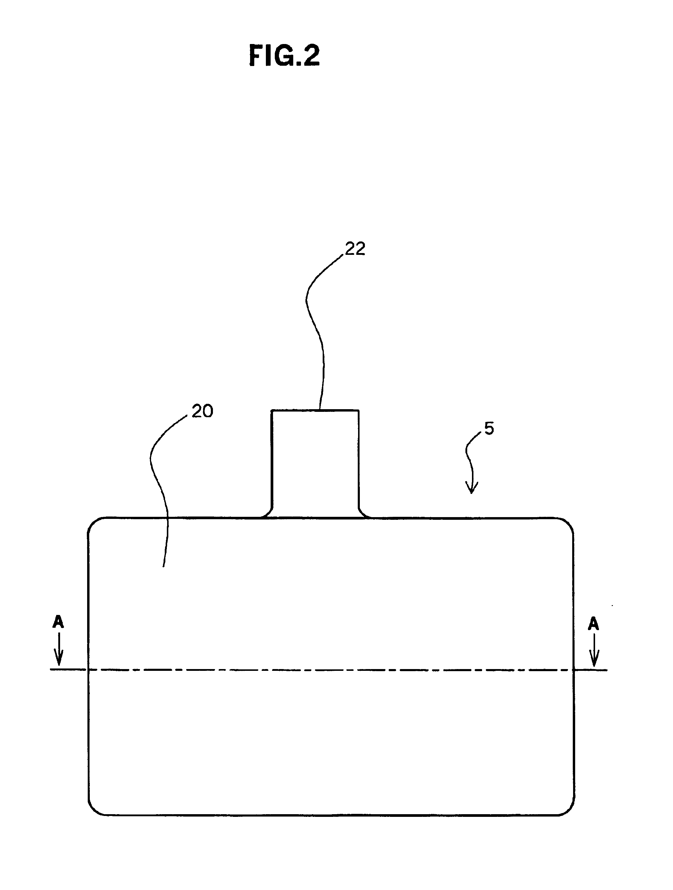
The pump body 5 includes the housing 20 having a blood inlet port 22 and a blood outlet port 23; a centrifugal fluid pump section 2 including an impeller 21 having a first magnetic material 25 and a second magnetic material 28 disposed therein and rotating in the housing 20 to feed a fluid by a centrifugal force generated during its rotation; an impeller rotational torque generation section 3 including a rotor 31 having a magnet 33 for attracting thereto the first magnetic material 25 of the impeller 21 and a motor 34 for rotating the rotor 31; an impeller position control section 4 having an electromagnet 41 (electromagnet for attracting the second magnetic mate...


PUM


Abstract

A centrifugal fluid pump apparatus includes a control mechanism; and a body 5 including a pump section having an impeller rotating inside a housing; a rotor having an impeller attraction magnet; a motor for rotating the rotor; an impeller attraction electromagnet for attracting the impeller thereto; an impeller-position detection sensor; and a groove for hydrodynamic bearing provided on an inner surface of the housing. The control mechanism has a position sensor output monitoring function or an electromagnet current monitoring function, a motor current monitoring function; and an emergency impeller rotation function. The impeller rotation function operates when the sensors or the electromagnet has a failure by using the position sensor output monitoring function or the electromagnet current monitoring function to rotate the impeller by utilizing the groove for hydrodynamic bearing.

Description

BACKGROUND OF THE PRESENT INVENTIONThe present invention relates to a centrifugal fluid pump apparatus for pumping a medical fluid, typically blood.In recent medical treatment, centrifugal blood pumps are increasingly used in artificial heart / lung units for extracorporeal blood circulation. Centrifugal pumps of the magnetic coupling type wherein a driving torque from an external motor is transmitted to an impeller through magnetic coupling are commonly used because the physical communication between the blood chamber of the pump and the exterior can be completely excluded and invasion of bacteria is prevented. The centrifugal blood pump includes a housing having a blood inlet port and a blood outlet port and an impeller rotatably accommodated in the housing to feed blood by a centrifugal force generated during its rotation. The impeller having a permanent magnet disposed therein is rotated by a rotor having magnets for attracting the magnet of the impeller thereto and by a rotationa...

Claims


Application Information

Patent Timeline
IPC IPC(8): A61M1/10F04D29/04F04D15/00F04D13/02F04D15/02F04D29/00F04D29/041F04D29/046F04D29/047F04D29/048F04D29/42
CPCA61M1/101A61M1/1036A61M1/1017F04D29/048A61M2205/3334A61M60/824A61M60/419A61M60/816A61M60/104A61M60/232A61M60/812A61M60/538A61M60/822
Inventor YAEGASHI, MITSUTOSHIASADA, TAKEHIKO
Owner TC1 LLC
Why Eureka
Try Eureka