

Processing method of tube body, manufacturing method of cylinder device and cylinder device manufactured by the same
a technology of cylinder device and manufacturing method, which is applied in the direction of spring/damper, mechanical apparatus, shock absorber, etc., can solve the problems of increasing work cost, affecting the quality of cylinder body parts, and affecting the quality of cylinder parts, so as to achieve accurate processing of the end portion of the tube body
- Summary
- Abstract
- Description
- Claims
- Application Information
AI Technical Summary
Benefits of technology
Problems solved by technology
Method used
Image

Examples
first embodiment
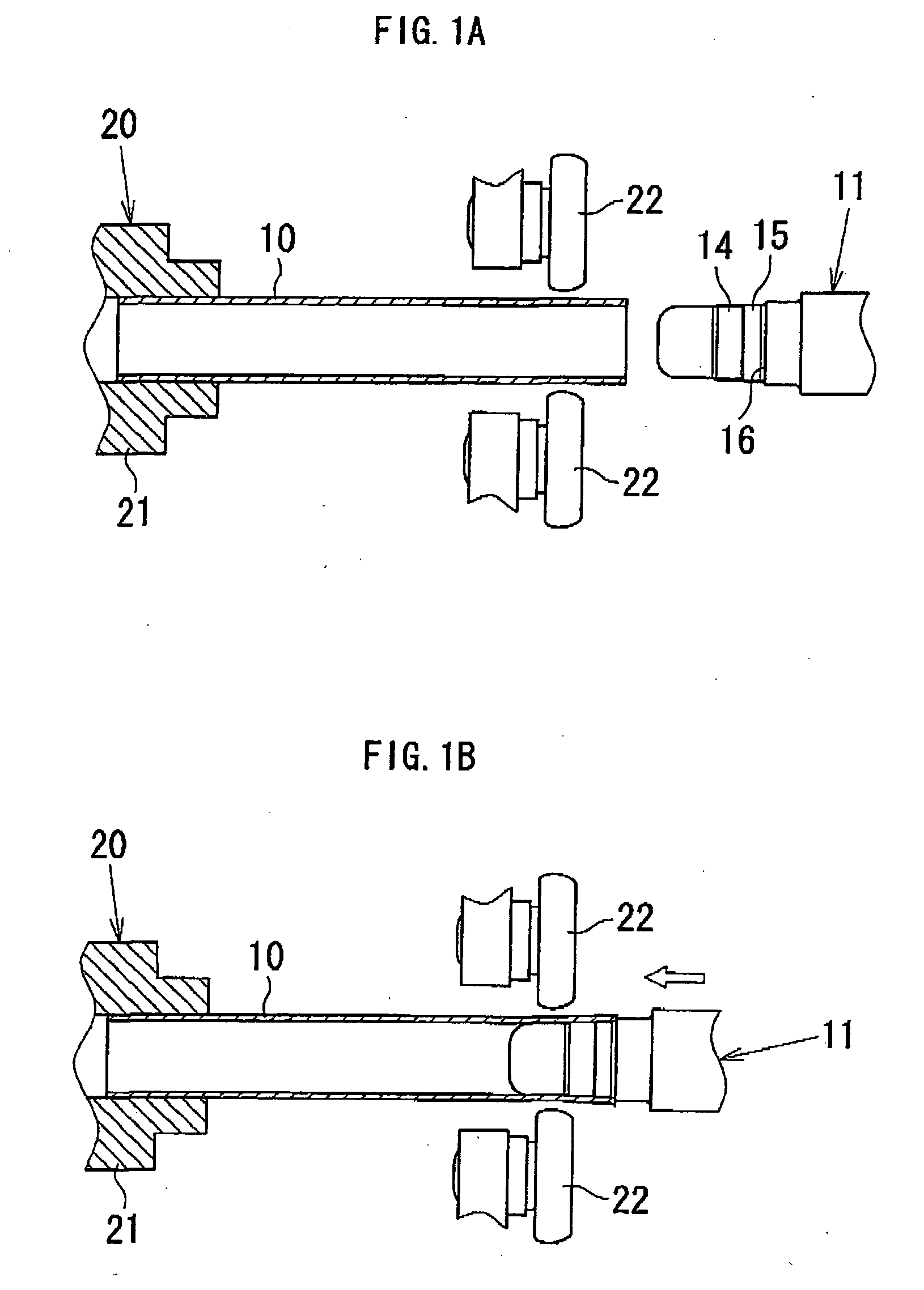
[0044]In the above first embodiment, the mandrel 11 with two steps made by the first forming portion 14 and the second forming portion 15 having different diameters was applied, but the number of the steps provided at the nose of the mandrel 11 is optional. If desired for thinner tubes, only one step may be applied, or if desired for more thick tube, three steps or more can be applied.
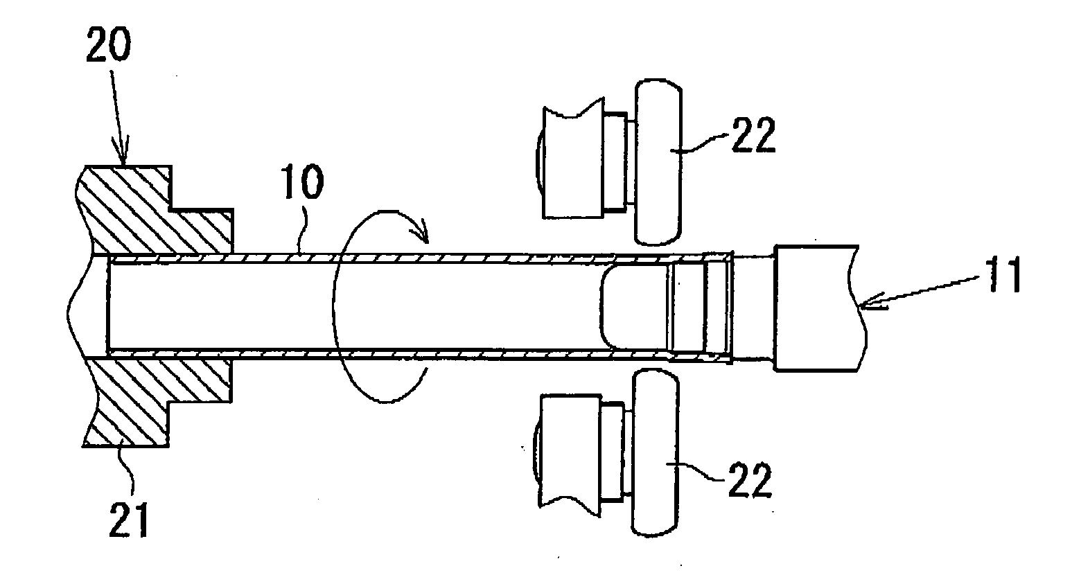
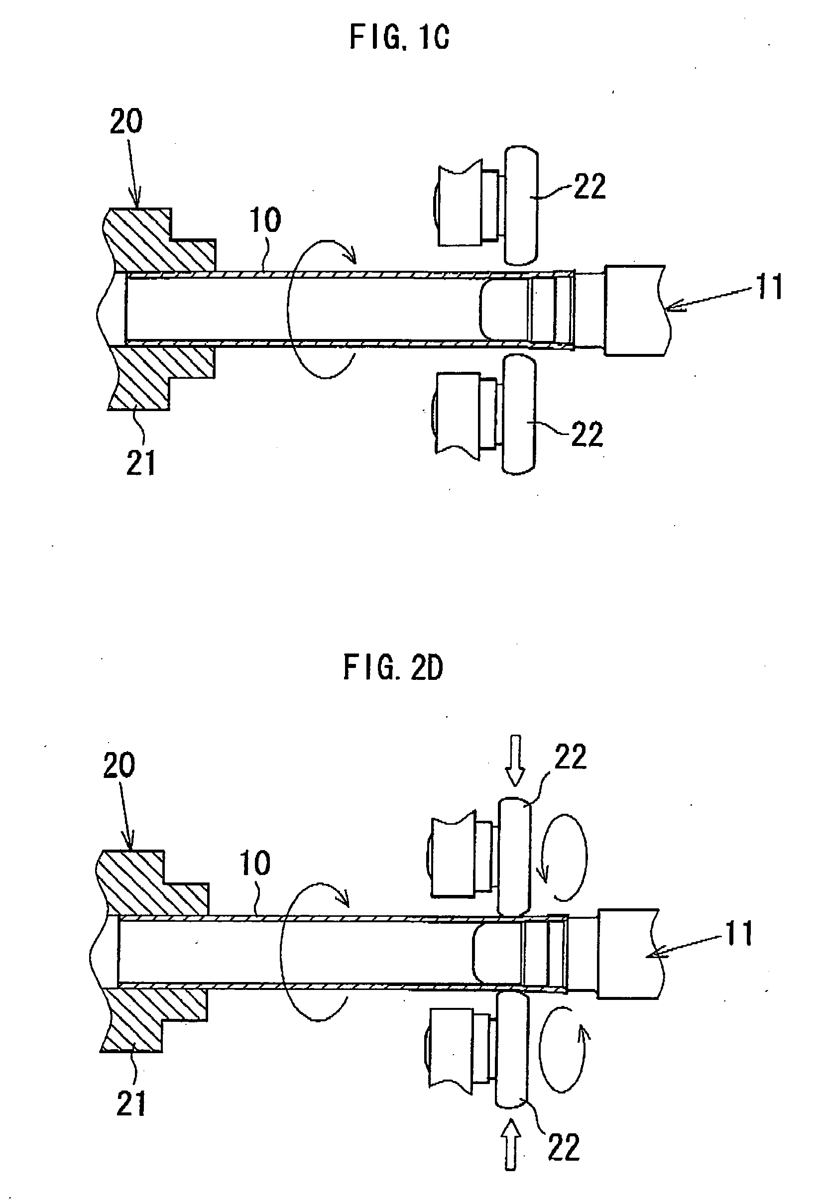
[0045]Further, in the embodiments hereinabove described, the pair of the roller dies 22 / 22 facing toward each other is used for the rotation ironing process; however, the number of the roller die 22 to be provided is also optional. Three roller dies 22 may be applied. Here, in case three roller dies 22 or more are applied, those roller dies 22 should be evenly arranged around the base tube 10. In addition, the present invention is applicable with a planetary ball die instead of the roller die.
[0046]In the first embodiment, the roller dies 22 / 22 are shifted along the base tube; however, the present inve...
second embodiment
[0051]In the second embodiment, as the same with the process shown in FIG. 1A, the base portion of the base tube 10 is to be supported by the chuck 21 of the chuck unit 20 provided within the rotation ironing process apparatus while the mandrel 11 is to be supported by a pressurized device (not shown) shiftable relative to the chuck unit 20. This FIG. 1A is thus the retaining process in the present invention. The rotation ironing process apparatus is provided with the pair of roller dies 22 / 22, each of the roller dies 22 / 22 is rotatable and placed to face each other with the base tube 10 retained by the chuck 21 between. The pair of roller dies 22 / 22 is supported by the driving device (not shown), so that each of the pair of roller dies 22 / 22 can come closer toward or away from each other. Further, the roller dies 22 / 22 are shiftable in parallel along the base tube 10. those roller dies 22 / 22 are not directly provided with a driving apparatus but rotated by rotation of the base tube...
PUM
| Property | Measurement | Unit |
|---|---|---|
| thickness | aaaaa | aaaaa |
| force | aaaaa | aaaaa |
| removing force | aaaaa | aaaaa |
Abstract
Description
Claims
Application Information