A protective nozzle mechanism

A gripper sheath and indenter technology, which is applied in the direction of manipulator, metal processing, metal processing equipment, etc., can solve the problem of easy damage of the suction nozzle, and achieve the effect of preventing the impact from falling.

Active Publication Date: 2018-01-12
BOZHON PRECISION IND TECH CO LTD
View PDF9 Cites 0 Cited by
  • Summary
  • Abstract
  • Description
  • Claims
  • Application Information

AI Technical Summary

Problems solved by technology

At the same time, in the prior art, the suction nozzle and the pressure head are integrated, and the suction nozzle is installed and maintained after absorbing small parts, which is easy to damage the suction nozzle.

Method used


Image

  • A protective nozzle mechanism
  • A protective nozzle mechanism
  • A protective nozzle mechanism

Examples


Embodiment Construction

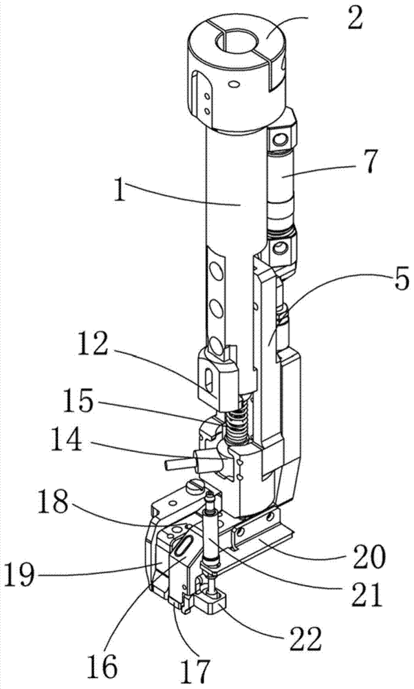
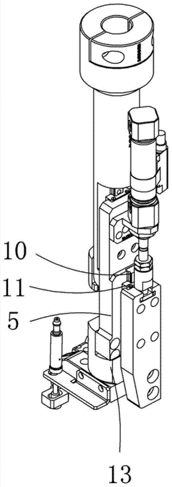
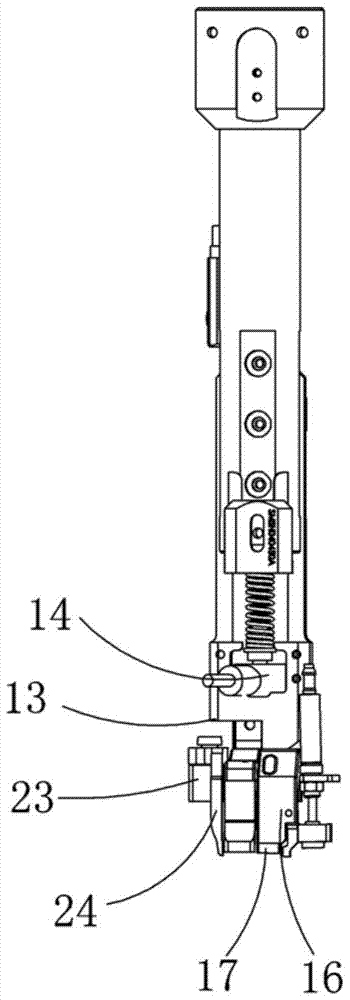
[0019] Examples, see attached Figure 1~4 , a suction nozzle mechanism with protection, including an R-axis extension shaft 1, a clamping block 2 is installed on the upper part of the R-axis extension shaft, the R-axis extension shaft and the manipulator can be locked and fixed by the clamping block, and the manipulator operates Drive the present invention to absorb parts and assemble the parts on the product, and then carry out pressure maintenance through the pressure head.

[0020] An R-axis slide rail 3 is installed on the right side of the R-axis extension shaft, an R-axis slider 4 is installed on the R-axis slide rail, and a connecting block 5 is installed on the R-axis slider. The upper part of the connecting block passes through the suction nozzle The cylinder fixing frame 6 is equipped with a suction nozzle cylinder 7; the piston rod lower end of the suction nozzle cylinder is connected to the pressure head connecting block 9 through a floating joint 8; the pressure h...


PUM


Abstract

The invention relates to a suction nozzle mechanism with a protection function. An R-axis sliding block is arranged on the right side of an R-axis extension shaft through an R-axis sliding rail and provided with a connecting block. A suction nozzle air cylinder is arranged on the upper portion of the connecting block through a suction nozzle air cylinder fixing frame. The lower end of the suction nozzle air cylinder is connected with a pressure head connecting block through a floating joint. The lower left portion of the R-axis extension shaft is provided with a pressure adjusting block. The lower end of the connecting block is connected with a weighing sensor through a weighing sensor seat. A connecting spring is connected between the pressure adjusting block and the weighing sensor. The lower end of the weighing sensor seat is provided with a suction nozzle seat. The lower end of the suction nozzle seat is provided with a suction nozzle. The lower end of the pressure head connection block is provided with a pressure head seat. The lower end of the pressing seat is provided with a pressure head. The right side of the suction nozzle seat is provided with a clamping jaw air cylinder through a clamping jaw air cylinder mounting frame. The lower end of the clamping jaw air cylinder is provided with a right clamping jaw jacket. The left side of the pressure head seat is provided with a left clamping jaw jacket through a left clamping jaw jacket fixing block. By the adoption of the suction nozzle mechanism, the suction nozzle can be protected, meanwhile the two edges of a part in the suction process are protected, and the small part is prevented from being impacted and dropping out.

Description

Technical field: [0001] The invention relates to the field of suction nozzle mechanism equipment, in particular to a protective suction nozzle mechanism. Background technique: [0002] When the suction nozzle is used to absorb small parts for assembly, the small parts on the suction nozzle may be hit and dropped. At this time, a protective component needs to be installed next to the suction nozzle to protect the small parts from impact. Simultaneously, in the prior art, the suction nozzle is integrated with the pressure head, and the suction nozzle is installed and kept under pressure after absorbing the small parts, so that the suction nozzle is easily damaged. Invention content: [0003] The purpose of the present invention is to address the shortcomings of the prior art and provide a protective suction nozzle mechanism, which uses a cylinder-separated suction nozzle mechanism to protect the suction nozzle; at the same time, the jaw cylinder moves to drive the right jaw ...

Claims


Application Information

Patent Timeline
Patent Type & Authority Patents(China)
IPC IPC(8): B23P19/00B25J15/06B25J19/06
CPCB23P19/00B25J15/06B25J19/06
Inventor 吕绍林朱晓锋杨艳伟李金柱田玉彪欧阳金
Owner BOZHON PRECISION IND TECH CO LTD
Why Eureka
Try Eureka