Rubber braking plate and manufacturing method thereof

A technology of brake pads and rubber, applied in the direction of brakes, brake components, vehicle parts, etc., can solve the problems of insufficient braking system, vehicle stop and failure, etc., to increase the sense of safety and driving confidence, and eliminate adverse psychological effects , safe and reliable performance

Inactive Publication Date: 2016-03-30
SUZHOU YINQUE INTELLIGENT TECH CO LTD
View PDF6 Cites 1 Cited by
  • Summary
  • Abstract
  • Description
  • Claims
  • Application Information

AI Technical Summary

Problems solved by technology

One of the major causes of traffic accidents is that the existing braking system of the vehicle is not effective enough. The existing braking system of the vehicle controls the driving of the vehicle by the limited friction generated by the contact between the tire and the ground, but due to the contact area between the tire and the ground Relatively small, the friction generated is not enough, so the vehicle cannot be stopped immediately, which greatly increases the probability of accidents
Taking an ordinary car as an example, assuming that the speed of the vehicle is 80mk / m, a pedestrian suddenly appears across the road ahead, the driver immediately takes braking measures, and the vehicle has to drive about 40m forward due to inertia to stop. If it is a heavy truck, Its inertia is greater, and the rushing distance is longer; and when driving in rainy days, snowy days, and icy roads, emergency braking usually causes a large uncontrollable slip, causing unimaginable dangers; in passenger and freight transportation In work, the performance of the braking system of the vehicle is directly related to the safety of human life and property. There are countless accidents directly caused by the failure of the braking system, especially on the long downhill section of the mountain road, due to the fatigue of the driver or improper operation, the brake pads are heated Carbonization leading to brake failure is also a common problem

Method used


Image

  • Rubber braking plate and manufacturing method thereof
  • Rubber braking plate and manufacturing method thereof
  • Rubber braking plate and manufacturing method thereof

Examples


Embodiment 1

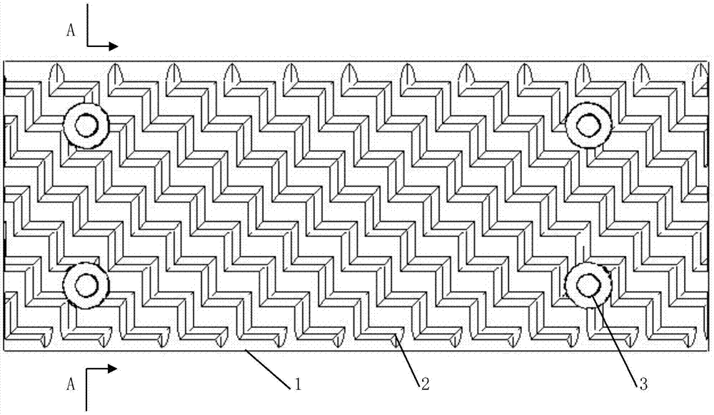
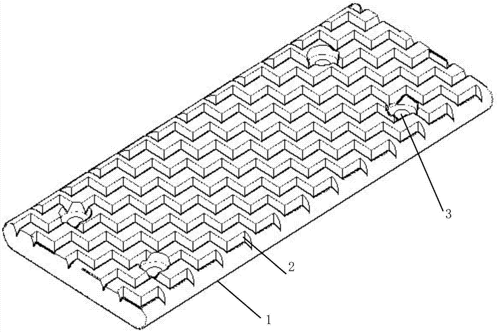
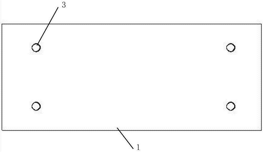
[0027] Embodiment 1: refer to attached Figure 1-6 , a kind of rubber brake pad 1 of the present invention, comprises plate body, and described plate body comprises reinforcement layer 4 and wear-resisting layer 5, and described reinforcement layer 4 is provided with criss-cross grid, and reinforcement layer 4 is provided with There is a wear-resistant layer 5, and the wear-resistant layer 5 is provided with a groove 2, and the described plate body is provided with a screw hole 3 or a buckle slot.

[0028] In a further preferred solution, the plate body is rectangular, the screw hole 3 is a countersunk hole, and the bolt 9 is connected to the brake plate fixing frame 8 through the screw hole 3, or connected to the brake plate fixing frame through a buckle slot.

[0029] In a further preferred solution, the wear-resistant layer 5 is provided with wavy grooves 2 or protrusions, and the depth of the grooves 2 or the height of the protrusions is 5-15mm.

[0030] In a further pref...


PUM

PropertyMeasurementUnit
heightaaaaaaaaaa

Abstract

The invention relates to a road traffic vehicles, in particular to a rubber braking plate and. The braking plate comprises a plate body, wherein the plate body comprises a reinforcing layer and a wear-resisting layer, wherein grids which are longitudinally and transversely staggered are arranged in the reinforcing layer; the wear-resisting layer is arranged on the upper surface of the reinforcing layer; grooves are formed in the wear-resisting layer; fixing screw holes or buckle clamping grooves are arranged in the plate body; the braking plate is arranged on the bottom of a vehicle by virtue of a holder; the braking plate is operated to lift by virtue of a hand brake rod; and the rubber braking plate achieves the braking effect by virtue of friction resistance with a road surface.

Description

technical field [0001] The invention relates to the field of road transport vehicles, in particular to a vehicle rubber brake plate and a manufacturing method thereof. Background technique [0002] With the development of society, the number of highway passenger and cargo transport vehicles has increased, and more traffic accidents have occurred at the same time, causing huge losses of life and property. One of the major causes of traffic accidents is that the existing braking system of the vehicle is not effective enough. The existing braking system of the vehicle controls the driving of the vehicle by the limited friction generated by the contact between the tire and the ground, but due to the contact area between the tire and the ground Relatively small, the friction generated is not enough, so the vehicle cannot be stopped immediately, which greatly increases the probability of accidents. Taking an ordinary car as an example, assuming that the speed of the vehicle is 80...

Claims


Application Information

Patent Timeline
Patent Type & Authority Applications(China)
IPC IPC(8): B60T1/14B29C39/10B29C39/26
CPCB60T1/14B29C39/10B29C39/26
Inventor 隆剑猛
Owner SUZHOU YINQUE INTELLIGENT TECH CO LTD
Why Eureka
Try Eureka