Vehicle-mounted curved rail lubricant lateral spraying device

A technology of spraying device and lubricant, which is applied in the directions of rail lubrication, rail wetting/lubrication, transportation and packaging, etc., can solve the problems that the lubricant cannot lubricate and reduce wear, pollute the rail and the ballast bed, and waste the lubricant, etc. Achieve the effect of extending service life, reducing waste and reducing wear and tear

Active Publication Date: 2017-09-29
济南三新铁路润滑材料有限公司
View PDF6 Cites 0 Cited by
  • Summary
  • Abstract
  • Description
  • Claims
  • Application Information

AI Technical Summary

Problems solved by technology

[0002] The vehicle-mounted curved rail lubricating coating device in the prior art is placed at the tail of the railway passenger train, and lubricating materials such as lubricant or grease are applied to the corners of the outer strands of the curved rail to achieve the contact between the wheel rim of the rolling stock and the rail. Lubricate and reduce friction on the frictional force surface, reduce the wear of the contact surface, and prolong the service life of the rail. With the continuous increase of the running speed of the train, in the prior art, the lubricant or grease is sprayed obliquely from the top of the rail The method can no longer meet the actual requirements of rail lubrication. When the nozzle is installed too high, the lubricant will be sprayed on the top surface of the rail, causing the locomotive to slip or the train stops; When the speed is too low, the lubricant is sprayed below the contact zone between the wheel rim and the rail. The lubricant does not have the effect of lubricating and reducing friction, which not only causes lubricant waste, but also pollutes the rail and track bed

Method used


Image

  • Vehicle-mounted curved rail lubricant lateral spraying device
  • Vehicle-mounted curved rail lubricant lateral spraying device
  • Vehicle-mounted curved rail lubricant lateral spraying device

Examples


Embodiment Construction

[0022] In order to better understand the present invention, the implementation manner of the present invention will be explained in detail below in conjunction with the accompanying drawings.

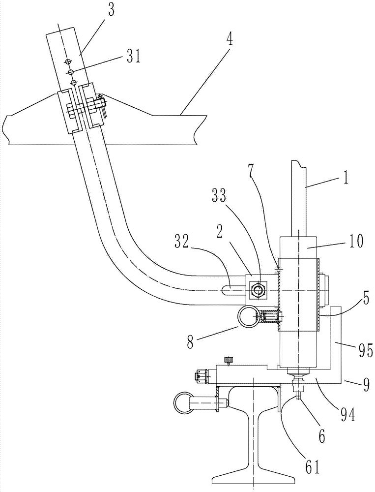
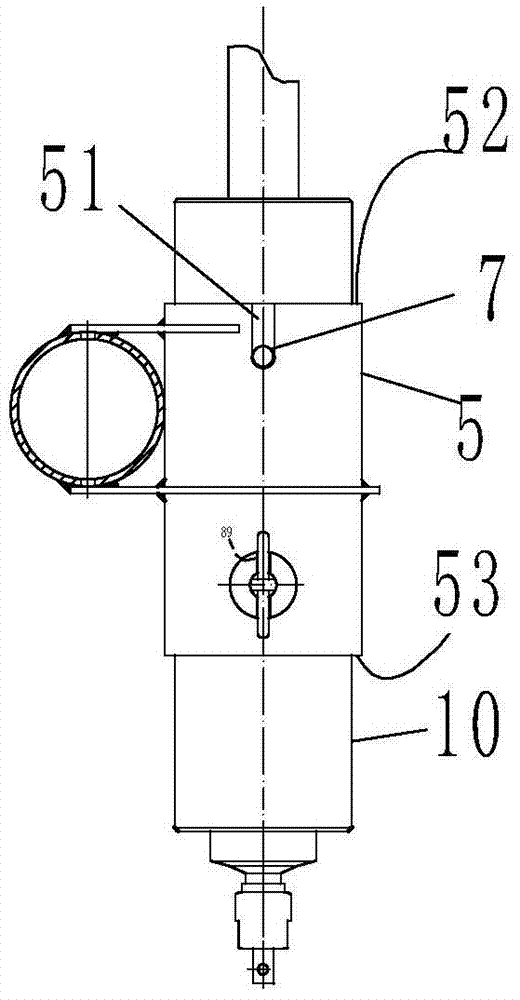
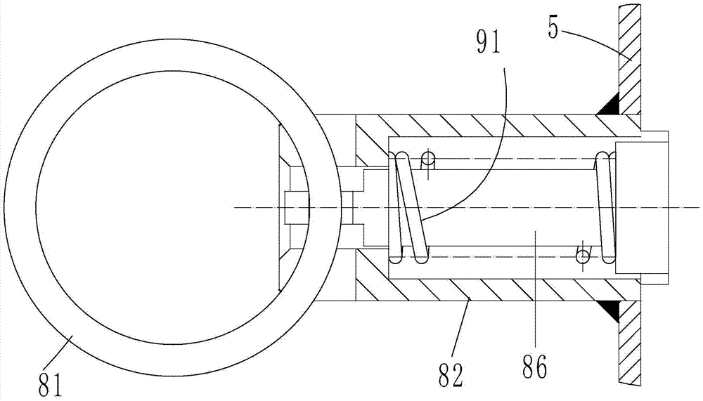
[0023] Such as Figure 1 to Figure 5 As shown, a vehicle-mounted curved rail lubricant lateral spraying device includes a height adjustment pipe 3, a snap ring 4, a horizontal adjustment pipe 2, an oil injection pipe 1, a top tightening structure 8, a wheel positioning structure 9, and a positioning sleeve 5 , positioning pin 7, side spray nozzle 6, the height adjustment pipe 3 is fixed on the axle box of the locomotive and vehicle, the height adjustment pipe 3 is an elbow, and the horizontal part of the elbow is provided with a horizontal adjustment near the end. Tube 2, the horizontal adjustment tube can adjust the axial position in the horizontal part of the elbow, the horizontal adjustment tube 2 is connected with the vertical positioning sleeve 5 of the vertically arranged round tu...


PUM


Abstract

The invention discloses a vehicle-mounted curve rail lubricating agent lateral spraying device. The vehicle-mounted curve rail lubricating agent lateral spraying device comprises a height position adjusting pipe and a lateral spraying nozzle, wherein the height position adjusting pipe is fixed to a rolling stock axle box; a horizontal adjusting pipe is arranged in the position, close to the end portion, of the horizontal part of a bent pipe and can be adjusted in the axial direction on the horizontal part of the bent pipe; the horizontal adjusting pipe is connected with a vertical positioning sleeve of a round pipe structure; a positioning groove is formed in the lateral wall of the upper portion of the vertical positioning sleeve; an axial positioning pipe is arranged in an inner hole of the vertical positioning sleeve; an oil spraying pipe is arranged inside the axial positioning pipe; the upper end of the oil spraying pipe is connected with a petrol pump; the lower end of the petrol pump is connected with the lateral spraying nozzle; a spout of the lateral spraying nozzle corresponds to the elongation position of an outer rail of a curve rail; a radial positioning pin is arranged on the outer wall of the positioning pipe and matched with the positioning groove. The friction stressed portion is accurately and effectively lubricated and coated, abrasion of the friction portion is reduced, the service life of the rail is prolonged, consumption of lubricating materials is reduced, and waste is reduced.

Description

technical field [0001] The invention relates to the technical field of railway rail lubrication coating equipment, in particular to a vehicle-mounted curved rail lubricant side spraying device. Background technique [0002] The vehicle-mounted curved rail lubricating coating device in the prior art is placed at the tail of the railway passenger train, and lubricating materials such as lubricant or grease are applied to the corners of the outer strands of the curved rail to achieve the contact between the wheel rim of the rolling stock and the rail. Lubricate and reduce friction on the frictional force surface, reduce the wear of the contact surface, and prolong the service life of the rail. With the continuous increase of the running speed of the train, in the prior art, the lubricant or grease is sprayed obliquely from the top of the rail The method can no longer meet the actual requirements of rail lubrication. When the nozzle is installed too high, the lubricant will be s...

Claims


Application Information

Patent Timeline
Patent Type & Authority Patents(China)
IPC IPC(8): B61K3/02
CPCB61K3/02
Inventor 曹传东李寅杰王旭华孙露曹爱提牟志爱马进国
Owner 济南三新铁路润滑材料有限公司
Why Eureka
Try Eureka