Composite joints and jibs

A technology of composite joints and jibs, which is applied to cranes and other directions, can solve problems such as uneven force on the jib section, and achieve the effect of improving the force transmission effect, improving performance, and uniform force

Active Publication Date: 2018-01-23
XCMG CONSTR MACHINERY
View PDF7 Cites 0 Cited by
  • Summary
  • Abstract
  • Description
  • Claims
  • Application Information

AI Technical Summary

Problems solved by technology

[0006] The purpose of the present invention is to provide a composite joint to solve the problem of uneven stress between the main chords or between the boom sections in the prior art when the boom sections of the boom frame are connected

Method used


Image

  • Composite joints and jibs
  • Composite joints and jibs
  • Composite joints and jibs

Examples


no. 1 example

[0045] The following will be based on Figure 9 and Figure 10 The composite joint 26 of the first embodiment of the present invention will be described in detail.

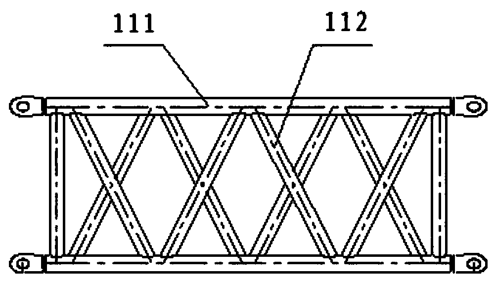
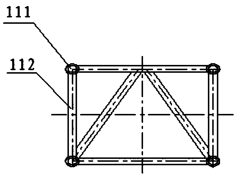
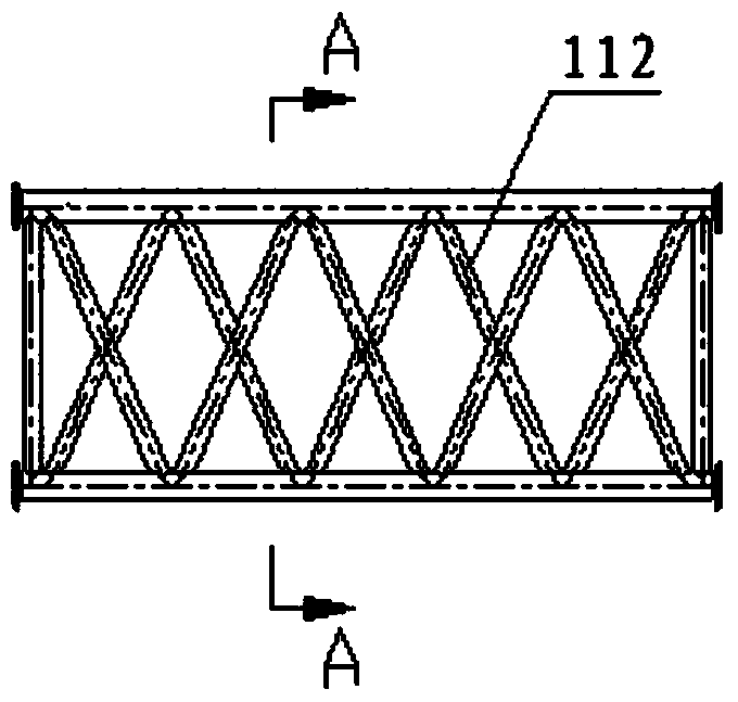
[0046] Such as Figure 9 As shown, the composite main chord of the jib section 21 is composed of two main chords 211 arranged in parallel in the longitudinal direction. The composite main chords of adjacent boom sections are connected with composite joints 26 . A lug joint 211A is correspondingly provided on the side of the two main chords of each composite main chord corresponding to the composite joint 26 .

[0047] Such as Figure 10 As shown, the composite joint 26 of the first embodiment includes a seat 261 . The seat body 261 has a first side and a second side ( Figure 10 The left side and the right side shown), the first side and the second side of the seat body 261 are fixedly connected with lug type taps 262 . The lug-type tap 262 in this embodiment is a multi-lug-type tap, and multiple lugs of ea...

no. 2 example

[0055] The following will be based on Figure 11 and Figure 12 The composite joint 26 of the second embodiment of the present invention will be described in detail.

[0056] Such as Figure 12 As shown, in the compound joint 26 of the second embodiment, the lug type tap 262 is also a multi-lug type tap. Different from the compound joint 26 of the first embodiment, the number of lugs of the lug type tap 262 arranged on the first side of the compound joint 26 in the second embodiment is different from that of the lug type tap 262 arranged on the second side. The connectors 262 have the same number of lugs.

[0057] Specifically, as Figure 12 As shown, the number of lugs of the lug tap 262 on both the first side and the second side of the compound joint 26 of the second embodiment is three.


PUM


Abstract

The invention discloses a composite connector and a cantilever crane. The composite connector comprises a base body and multiple ear plate-type sub connectors; the base body is provided with a first side surface and a second side surface which are oppositely arranged; and the multiple ear plate-type sub connectors are separately arranged on the first side surface and the second side surface of the base body and are fixedly connected with the base body, wherein at least one of the first side surface and the second surface is provided with more than two ear plate-type sub connectors. Jib sections provided with composite type main chords are connected to form the cantilever crane through the above composite connectors; the stress applied to the main chords can be transferred to the main chords on different planes through the base bodies; and the stress transferring effect among the main chords is improved, so that the stress among the multiple jib sections is more uniform, and the performance of the cantilever crane is improved.

Description

technical field [0001] The invention relates to the field of cranes, in particular to a compound joint and a jib. Background technique [0002] With the rapid development of the international energy and chemical engineering construction field, the requirements for modularization, large-scale and integrated hoisting in the project are constantly increasing, and higher requirements are put forward for the lifting capacity and lifting moment of lifting equipment. The jib is the main load-bearing part of the lifting equipment, and its own structural form, bearing capacity and other characteristics directly affect the use performance and lifting performance of the whole machine. [0003] The jib frame of the lifting equipment is generally connected by successively arranged jib sections. Such as figure 1 and figure 2 As shown, the jib section in the prior art is generally a truss structure formed by tailor-welding of four main chords 111 and several webs 112 . However, with t...

Claims


Application Information

Patent Timeline
Patent Type & Authority Patents(China)
IPC IPC(8): B66C23/64
CPCB66C23/64
Inventor 肖猛周玉龙刘玉泉
Owner XCMG CONSTR MACHINERY
Why Eureka
Try Eureka