Bushing friction and wear test device

A friction and wear test, bushing technology, applied in the direction of measuring devices, wear resistance testing, instruments, etc., can solve the problems of bushing friction unevenness, long test period, unable to simulate, etc., to reduce test cost, simple structure, The effect of improving efficiency

Active Publication Date: 2020-11-24
XCMG EXCAVATOR MACHINERY
View PDF32 Cites 0 Cited by
  • Summary
  • Abstract
  • Description
  • Claims
  • Application Information

AI Technical Summary

Problems solved by technology

According to the movement principle of the slider crank mechanism, when the slider is the active part, it is easy to get stuck, so when the device moves to the dead point, it is easy to get stuck, and the existing technology still cannot simulate the actual working conditions, and the friction of the bushing is not good. Uniformity, the problem of long test period

Method used


Image

  • Bushing friction and wear test device
  • Bushing friction and wear test device
  • Bushing friction and wear test device

Examples


Embodiment Construction

[0017] The present invention will be further described below according to the accompanying drawings and embodiments.

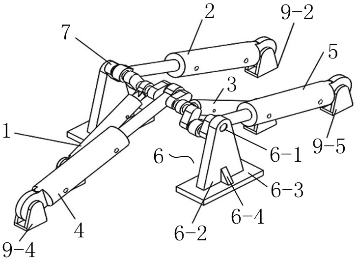
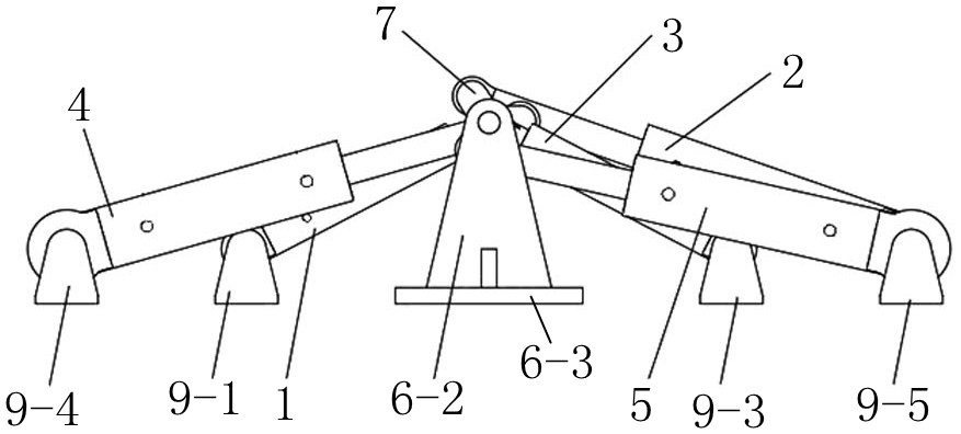
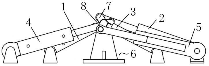
[0018] Such as Figure 1 to Figure 3 As shown, a bushing friction and wear test device includes a crankshaft 7 and crankshaft mounts 6 supported at both ends of the crankshaft 7. The crankshaft 7 is provided with a plurality of eccentric parts, and the crankshaft 7 is detachably connected as a whole by the plurality of eccentric parts. , during the test, the crankshaft 7 needs to be disassembled, and the bushing 8 to be tested is installed between the eccentric part of the crankshaft 7 and the shaft center of the piston rod of the test oil cylinder, and each eccentric part of the crankshaft 7 is evenly distributed in the circumferential direction That is, according to the number of eccentric parts on the crankshaft 7, the spatial deflection angle of adjacent eccentric parts is determined. If there are three eccentric parts, the angle between the three eccentri...


PUM


Abstract

The invention belongs to the technical field of workpiece wear test devices. The invention particularly relates to a bushing friction and wear test device which comprises a crankshaft and crankshaft mounting seats supported at two ends of the crankshaft, a plurality of eccentric parts are arranged on the crankshaft; the crankshaft is formed by detachably connecting a plurality of eccentric parts into a whole; each eccentric part of the crankshaft is sequentially and uniformly deflected and distributed in the circumferential direction; the number of eccentric parts of the crankshaft is not lessthan three; the two end parts of the crankshaft are coaxial; the end part of the crankshaft is mounted in the mounting hole of the crankshaft mounting seat; each eccentric part of the crankshaft is provided with a test oil cylinder, the test oil cylinders are arranged on the two sides of the crankshaft in a crossed mode, a force application oil cylinder is installed on the concentric part, between every two adjacent test oil cylinders, of the crankshaft, the force application oil cylinders are arranged on the two sides of the crankshaft in a crossed mode, and the test oil cylinders and the force application oil cylinders are hinged and fixed through corresponding oil cylinder mounting bases. The test device can be used for carrying out a wear test on a plurality of bushings at one time, so that the working efficiency is greatly improved.

Description

technical field [0001] The invention belongs to the technical field of workpiece wear test devices, and in particular relates to a bush friction and wear test device. Background technique [0002] In the prior art, the slider-crank mechanism is used to install the bushing at the hinge point between the cylinder and the crank, and the piston rod moves to drive the crank to swing to realize the wear test of the bushing. The bushing is installed at the hinge point of the crank and the fixed oil cylinder, and the fixed oil cylinder pulls the connecting shaft between the crank and the fixed oil cylinder to cause deformation to realize the friction and wear test of the bushing. The existing technology can only do one bushing wear test at a time. During the movement, the movable cylinder is the active part, and the movement of the piston rod of the movable cylinder drives the crank to swing back and forth. According to the movement principle of the slider crank mechanism, when the...

Claims


Application Information

Patent Timeline
Patent Type & Authority Applications(China)
IPC IPC(8): G01N3/56G01N3/02
CPCG01N3/56G01N3/02G01N2203/0048G01N2203/0258G01N2203/0676G01N2203/0682
Inventor 巩亚飞肖云博曹西朴王修通张昆秦强
Owner XCMG EXCAVATOR MACHINERY
Why Eureka
Try Eureka