Closestool flushing method

A technology for toilets and urinals, applied in the field of sanitary ware, can solve the problems of wasting water resources, poor flushing performance, small injection pressure and flow rate, etc., and achieves the effect of promoting the generation of siphons, the injection effect is stable, and the maintenance is continued.

Inactive Publication Date: 2016-03-30
XIAMEN R&T PLUMBING TECH
View PDF10 Cites 5 Cited by
  • Summary
  • Abstract
  • Description
  • Claims
  • Application Information

AI Technical Summary

Problems solved by technology

[0003] Since the water flows out from the cleaning outlet hole and the spray outlet hole at the same time, on the one hand, the amount of water allocated to the cleaning outlet hole and the injection outlet hole cannot reach the best effect. The amount of water flowing out of the water outlet hole cannot be kept relatively stable, and may be more or less, resulting in an unstable cleaning effect on the inner wall of the toilet bowl or an unstable jet flushing effect on the bottom of the toilet bowl; The flushing water flowing out of the water outlet hole must first wash the inner wall of the toilet bowl before flowing into the water seal at the bottom of the toilet bowl. Simultaneously supplying water to the cleaning water outlet hole and the jet water outlet hole will cause the washing water to not flow to the toilet bowl In the water seal at the bottom of the urinal, the spray h...

Method used


Image

  • Closestool flushing method
  • Closestool flushing method
  • Closestool flushing method

Examples


Embodiment Construction

[0028] In order to make the technical problems, technical solutions and beneficial effects to be solved by the present invention clearer and clearer, the present invention will be further described in detail below with reference to the accompanying drawings and embodiments. It should be understood that the specific embodiments described here are only used to explain the present invention, but not to limit the present invention.

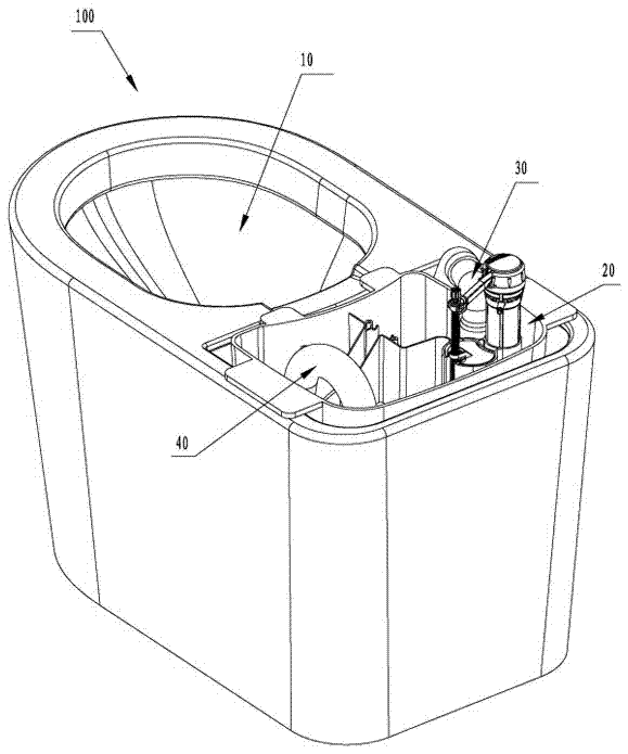
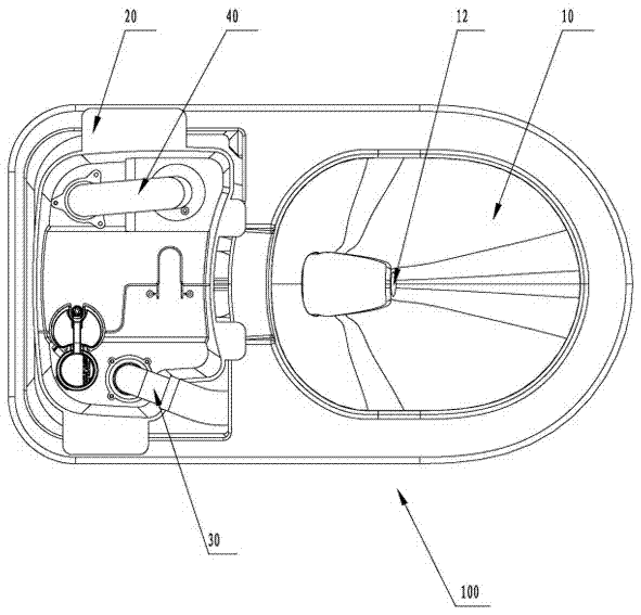
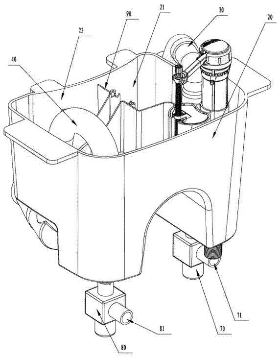
[0029] Please check Figure 1 to Figure 5 , A toilet 100 of the present invention, the toilet 100 includes a toilet body 10 with a toilet, a water storage tank 20, a washing pipe 30 and a jet pipe 40, the bottom of the water storage tank 20 is provided with a first jet flow increase The cleaning pipe 30 connects the outlet of the first jet flow increaser 50 and the cleaning water outlet 11 located on the upper part of the toilet bowl 100 and the second jet flow increaser 60. The cleaning water outlet hole of this embodiment 11 are arranged at intervals ...


PUM


Abstract

The invention discloses a closestool flushing method. The method comprises the following steps that 1, a flushing signal generated due to starting of a user is received through a control unit; 2, the control unit starts a valve unit, and a cleaning pipeline of a closestool is kept in a water-running state for T1 seconds; 3, after the cleaning pipeline is kept in the water-running state for T1 seconds, the control unit controls the valve unit, so that the valve unit stops water supply to the cleaning pipeline, and meanwhile a jetting pipeline of the closestool is kept in the water-running state for T2 seconds; 4, after the jetting pipeline is kept in the water-running state for T2 seconds, the control unit controls the valve unit, so that the valve unit stops water supply to the jetting pipeline, and meanwhile the cleaning pipeline is kept in the water-running state once more for T3 seconds; 5, after the cleaning pipeline is kept in the water-running state once more for T3 seconds, the control unit switches off the valve unit to end a flushing control program. By the adoption of the flushing steps, the flushing procedure is operated in a phased mode, the good siphon effect can be generated, water can be saved to a certain extent, in particular, the flushing performance at the time of low pressure is improved, and the method is simple, feasible and obvious in effect.

Description

Technical field [0001] The invention relates to a toilet flushing method in the field of sanitary ware. Background technique [0002] Most of the existing siphon toilets include a washing water outlet at the top of the toilet bowl and a spray water outlet at the bottom of the toilet bowl. The water flowing from the washing water outlet is used to clean the inner wall of the toilet. The water flowing out from the jetting hole is used to spray the bottom of the toilet bowl to generate siphon so as to transport the dirt on the inner wall of the toilet bowl and the bottom of the toilet to the sewage bend. When flushing, water is generally allowed to flow out from the flushing water outlet hole and the jetting water outlet at the same time to simultaneously wash the inner wall of the toilet bowl and spray the bottom of the toilet bowl to generate siphon until the flushing is completed. [0003] Since water flows out from the washing outlet and the jet outlet at the same time, on the on...

Claims


Application Information

Patent Timeline
IPC IPC(8): E03D1/28E03D1/38E03D5/10
CPCE03D1/28E03D1/38E03D5/10E03D2201/30
Inventor 刘梓光陈海滨钟志军
Owner XIAMEN R&T PLUMBING TECH
Why Eureka
Try Eureka