
Economical thermal power plant ammonia-containing wastewater treatment system and economical thermal power plant ammonia-containing wastewater treatment method

A wastewater treatment system and thermal power plant technology, applied in water/sewage treatment, water treatment parameter control, degassed water/sewage treatment, etc., can solve the problems of undeveloped use of struvite, high operation requirements, and high cost of chemicals. Achieve the effects of improving the removal rate and efficiency of ammonia nitrogen, avoiding high vapor-liquid ratio, and avoiding secondary pollution

Active Publication Date: 2016-06-15
XIAN TPRI WATER & ENVIRONMENTAL PROTECTION
View PDF6 Cites 2 Cited by
  • Summary
  • Abstract
  • Description
  • Claims
  • Application Information

AI Technical Summary

Problems solved by technology

The biological method and ion exchange method are not suitable for treating high-concentration ammonia nitrogen wastewater; the break point chlorination method has high operational requirements, high cost of chemicals, and harmful gases will be generated from intermediate products; the investment cost of stripping / stripping method and ammonia distillation method is high, High energy consumption may cause secondary pollution; the struvite method requires a large amount of medication and high cost, and the use of struvite remains to be developed

Method used


Image

  • Economical thermal power plant ammonia-containing wastewater treatment system and economical thermal power plant ammonia-containing wastewater treatment method

Examples


Embodiment 1

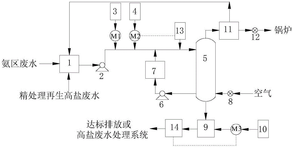
[0030] Ammonia zone wastewater (ρ(NH 3 -N): 150mg / L~250mg / L) and refined treatment of regenerated high-salt wastewater (ρ(NH 3-N): 1200mg / L~5000mg / L) are transported by the wastewater transport pump respectively, and mixed in the regulating tank 1 to form ammonia-containing wastewater, and the ammonia-containing wastewater is transported to the deamination tower 5 by the wastewater lifting pump 2, and deamination The deammonization agent in the agent storage tank 3 and the liquid caustic soda in the liquid caustic soda storage tank 4 enter the deammonization tower 5 after being mixed with the ammoniacal waste water through the deammonization agent metering pump M1 and the liquid caustic soda metering pump M2 respectively, and the deammonization tower 5. A second online pH meter 13 is provided at the entrance of the top, and the second online pH meter 13 is interlocked with the liquid caustic metering pump M2 for chain control, so that the pH of the mixed liquid entering the de...


PUM


Abstract

The invention discloses an economical thermal power plant ammonia-containing wastewater treatment system and an economical thermal power plant ammonia-containing wastewater treatment method. The economical thermal power plant ammonia-containing wastewater treatment system comprises a regulation basin, a deaminizating agent storage tank, a caustic soda liquid storage tank, an ammonia-removing column, an acid storage tank, a clean water basin, a steam-water separation device, a draught fan, a high-salinity wastewater treatment system and a centrifugal fan; the outlet of the regulation basin, the outlet of the deaminizating agent storage tank and the outlet of the caustic soda liquid storage tank communicate with the inlet of the top of the ammonia-removing column, both the outlet of a slurry basin of the bottom of the ammonia-removing column and the outlet of the acid storage tank communicate with the inlet of the clean water basin, the air outlet of the top of the ammonia-removing column communicates with the inlet of the steam-water separation device, the liquid outlet of the steam-water separation device communicates with the inlet of the regulation basin, the gas outlet of the steam-water separation device communicates with an external device through the draught fan, the outlet of the clean water basin communicates with the inlet of the high-salinity wastewater treatment system, and the air outlet of the centrifugal fan communicates with the air inlet of the slurry basin of the bottom of the ammonia-removing column. The invention can effectively treat ammonia area wastewater and fine treatment regenerated high-salinity wastewater, and moreover, the cost is low.

Description

technical field [0001] The invention belongs to the field of energy saving and environmental protection, and relates to an ammonia-containing wastewater treatment system and method, in particular to an economical thermal power plant ammonia-containing wastewater treatment system and method. Background technique [0002] Thermal power plants are large industrial water users, with a large amount of water consumption and discharge. In recent years, with the tightening of environmental protection and emission reduction policies, the pressure of thermal power enterprises to discharge waste water is increasing day by day. In April 2015, the "Water Pollution Prevention and Control Action Plan" was released, with unprecedented strict requirements on wastewater discharge standards and total pollutant discharge. Environmentally sensitive indicators such as ammonia nitrogen have become compulsory control items for thermal power plant wastewater discharge. [0003] Ammonia-containing w...

Claims


Application Information

Patent Timeline
Patent Type & Authority Applications(China)
IPC IPC(8): C02F9/04C02F101/16
CPCC02F1/20C02F1/586C02F1/66C02F9/00C02F2101/16C02F2209/06
Inventor 胡大龙苏艳王正江杨永翟绍晶
Owner XIAN TPRI WATER & ENVIRONMENTAL PROTECTION
Learn More