
Electronic pump

An electronic pump and rotor technology, applied in the field of centrifugal pumps, can solve the problems of reducing component life, energy loss, large friction, etc., and achieve the effect of reducing friction loss and improving service life

Active Publication Date: 2016-03-30
ZHEJIANG SANHUA AUTOMOTIVE COMPONENTS CO LTD
View PDF7 Cites 3 Cited by
  • Summary
  • Abstract
  • Description
  • Claims
  • Application Information

AI Technical Summary

Problems solved by technology

In this way, the pressure on the back cover of the impeller is greater than that on the front cover of the impeller, and a resultant force is generated to push the impeller to the pump inlet, so that the impeller and the device for axial limit (such as: circlip, bearing, etc.) are tight. Pressed together to generate greater friction, loss of energy, but also reduce the life of related components

Method used


Image

  • Electronic pump
  • Electronic pump
  • Electronic pump

Examples


Embodiment Construction

[0029] The present invention will be further described below in conjunction with accompanying drawing and specific embodiment:

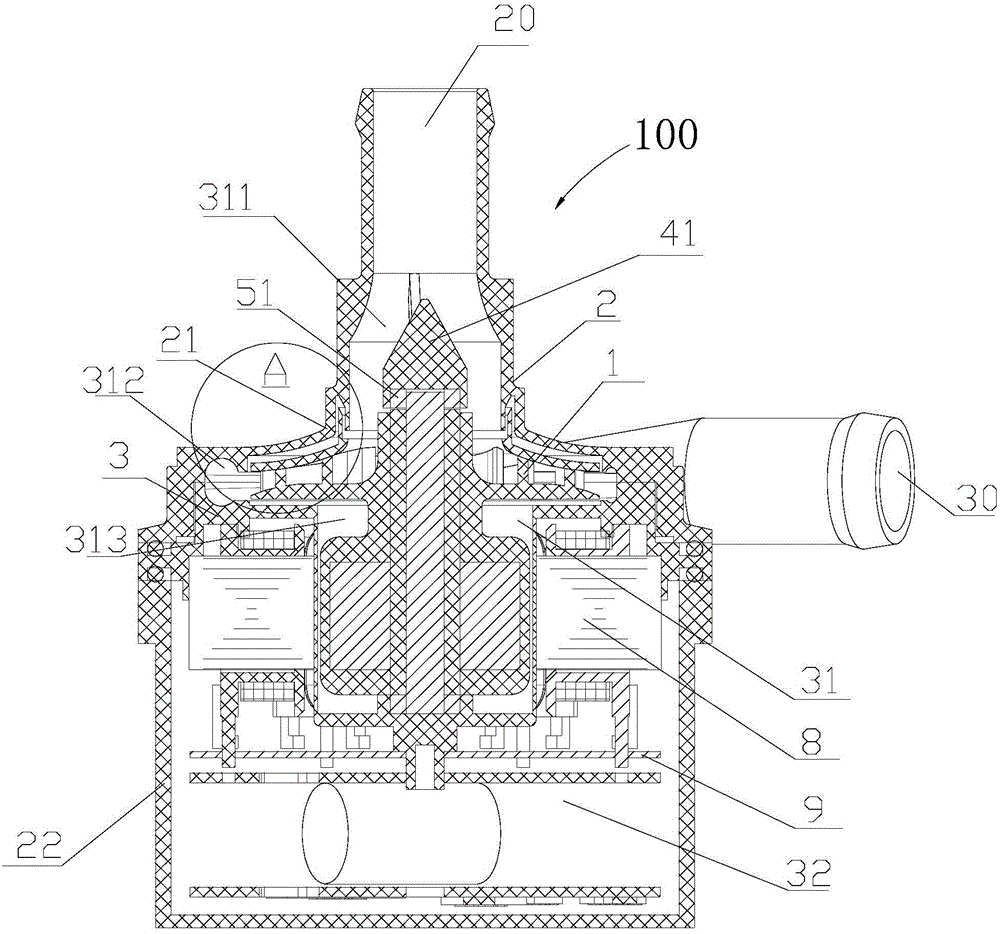
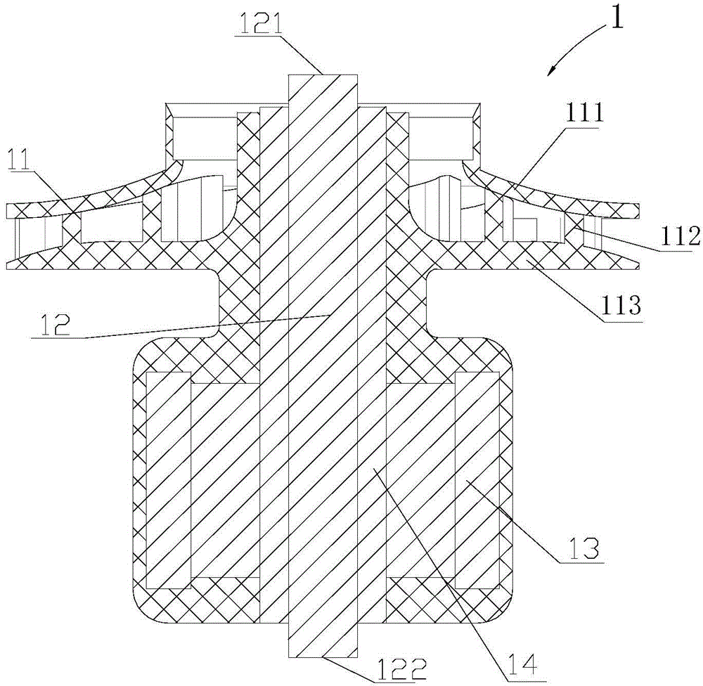
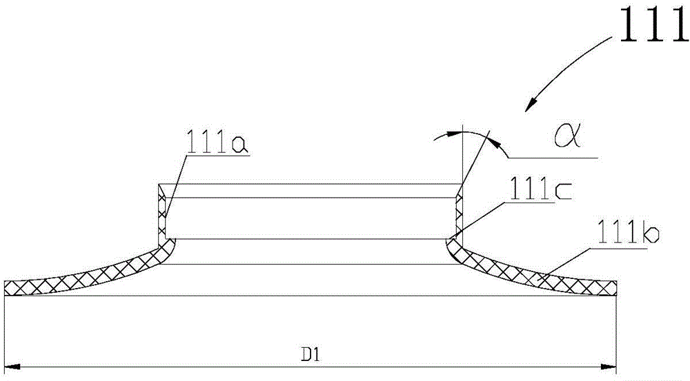
[0030] Such as Figure 1 to Figure 12 As shown, the electronic pump 100, 200, 300, 400 includes a rotor part 1, an outer casing 2, a separation sleeve 3, a stator part 8, and a circuit board 9; the outer casing 2 includes a first casing 21 and a second casing 22, and the rotor The component 1 includes a pump shaft 12, an impeller 11 and a rotor 13; the first housing 21 and the second housing 22 form the inner cavity of the electronic pump 100, and the separation sleeve 3 divides the inner cavity of the electronic pump 100 into two independent cavities, The two independent chambers are respectively: a wet chamber 31 for the circulation of the working medium and a dry chamber 32 where the working medium does not enter; the wet chamber 31 is formed by sealing between the first housing 21 and the separation sleeve 3, and the second housing 22 The dry ca...


PUM


Abstract

Disclosed is an electronic pump. The electronic pump comprises a first shell body, a separation sleeve, a second shell body, a rotor component and a stator component. The rotor component comprises an impeller, a pump shaft and a rotor. The first shell body and the second shell body are arranged oppositely in a sealed mode to form the inner cavity of the electronic pump. The electronic pump further comprises an axial limiting device which is used for limiting axial motion of the impeller toward the first tail end of the pump shaft. The impeller comprises vanes and a rear impeller covering plate. The electronic pump further comprises an axial force balance structure which comprises a pressure discharging hole penetrating through the rear impeller covering plate. The pressure discharging hole is communicated with a low-pressure area where an inlet is located and a high-pressure area where the rotor is located. The axial force balance structure further comprises a convex ring and an annular groove. The convex ring is formed in the position, close to an outlet, of the rear impeller covering plate and in the reverse direction toward the inlet. The annular groove is formed in the second shell body in correspondence with the convex ring. The convex ring is inserted in the inner cavity of the annular groove. In this way, the axial force balance structure is arranged, so that axial thrust and part abrasion are reduced, and the service life of is prolonged.

Description

【Technical field】 [0001] The invention relates to a centrifugal pump, in particular to an electrically driven centrifugal pump. 【Background technique】 [0002] Typically, electronic pumps are used to transport fluid working fluids. The working medium in the pump is driven by the impeller to rotate together, and is thrown to the edge of the pump casing under the action of centrifugal force, thereby generating a certain pressure, and then flows out from the outlet or pipe; the center of the impeller is thrown out due to the working medium The pressure is reduced, so that the upstream working medium is sucked into the pump cavity through the water pipe under the action of the pressure difference between the inlet of the pump cavity and the center of the impeller. Therefore, the transportation of working fluid is realized. The impeller of the electronic pump is connected to the rotor. When the rotor is driven to rotate by the electromagnetic force existing between the rotor an...

Claims


Application Information

Patent Timeline
Patent Type & Authority Applications(China)
IPC IPC(8): F04D13/06F04D29/041F04D29/66
Inventor 不公告发明人
Owner ZHEJIANG SANHUA AUTOMOTIVE COMPONENTS CO LTD
Learn More