
A control device and control method for an inverter cooling fan

A cooling fan and control method technology, applied in pump control, engine control, non-variable pumps, etc., can solve problems such as frequent changes in fan speed, difficulty in setting a reasonable temperature reference value, and difficulty in realizing a preset temperature/speed curve

Active Publication Date: 2017-03-22
NR ELECTRIC CO LTD +2
View PDF9 Cites 0 Cited by
  • Summary
  • Abstract
  • Description
  • Claims
  • Application Information

AI Technical Summary

Problems solved by technology

[0006] The purpose of the present invention is to provide a control device and control method for an inverter cooling fan, which is used for cooling the inverter power device, and can solve the problem of frequent changes in the fan speed and difficulty in setting a reasonable temperature reference value in the prior art. When the temperature change rate is large, it is easy to over-temperature operation, and there are many preset temperature / speed curves that are difficult to realize, etc.

Method used


Image

  • A control device and control method for an inverter cooling fan
  • A control device and control method for an inverter cooling fan
  • A control device and control method for an inverter cooling fan

Examples


Embodiment Construction

[0033] In order to make the object, technical solution and advantages of the present invention clearer, the present invention will be further described in detail below in conjunction with the accompanying drawings and embodiments. It should be understood that the specific embodiments described here are only used to explain the present invention and not to limit the present invention.

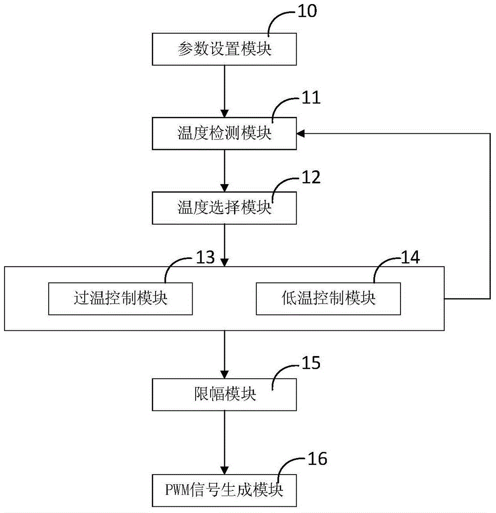
[0034] Such as figure 1 As shown, the present invention provides a control device for an inverter cooling fan, wherein the cooling fan is mainly aimed at a DC fan, and can accept pulse width modulation (PWM) signals with different duty ratios to adjust the speed in real time; the control device includes The parameter setting module 10, the temperature detection module 11, the temperature selection module 12, the over-temperature control module 13, the low-temperature control module 14, the limiter module 15 and the PWM signal generation module 16 are respectively introduced below.

[0035] The ...


PUM


Abstract

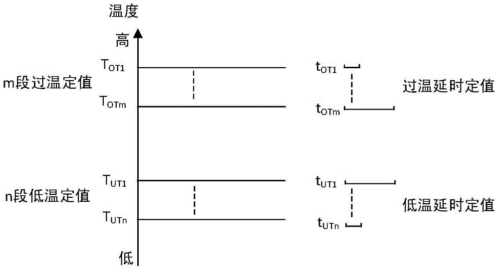
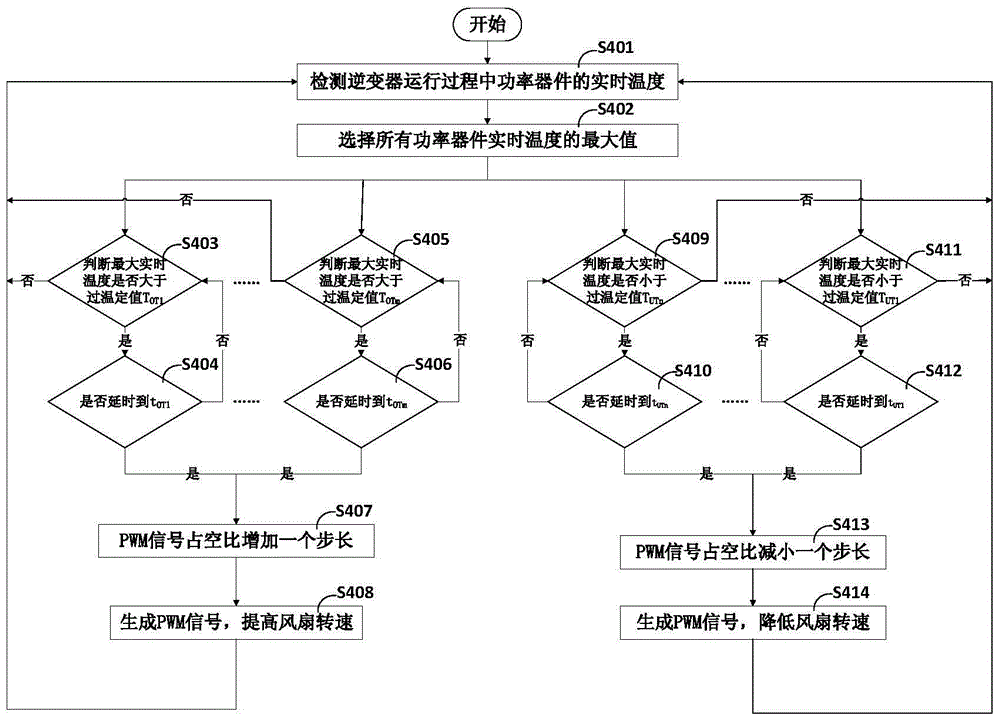
The invention discloses a control method for an inverter cooling fan. The method comprises the following steps: detecting the real-time temperature of all power devices of an inverter in the running process; selecting the maximum real-time temperature of all the power devices; if the maximum real-time temperature exceeds the set over-temperature value of each section and the time that the maximum real-time temperature continuously remains exceeding the set over-temperature value reaches the corresponding set delay value, increasing one step for PWM (Pulse-Width Modulation) duty ratio, and increasing the rotating speed of the fan; if the maximum real-time temperature is less than the set low-temperature value of each section and the time that the maximum real-time temperature remains being less than the set low-temperature value reaches the corresponding set delay value, decreasing one step for the PWM duty ratio, and decreasing the rotating speed of the fan; if both the aforementioned determining conditions are not met, maintaining the current rotating speed of the fan. The method is applied to the cooling of the power devices of the inverter and can solve the problems in the prior art, such as that the rotating speed of the fan frequently varies, the temperature reference value is not easy to reasonably set, the fan easily runs at over-temperature if the temperature varies a lot, and a plurality of preset temperature / rotating speed curves are provided and difficult to realize. The invention further discloses a control device for the inverter cooling fan.

Description

technical field [0001] The invention belongs to the field of fan control, and in particular relates to a control device and a control method of a DC fan for inverter heat dissipation. Background technique [0002] In small and medium power inverters, DC fans are usually used to dissipate heat from power devices to reduce their operating temperature and ensure the normal operation of the inverter. The speed control method of the current DC fan is pulse width modulation (PWM) control, and its control principle is: provide a square wave signal to the control line of the fan, and control the speed of the fan by adjusting the duty cycle of the square wave signal. [0003] The following methods are commonly used to control the speed of DC fans: one method is constant temperature control, which sets a desired temperature reference value, and through closed-loop control, automatically adjusts the duty cycle of the PWM signal according to the temperature reference value to maintain t...

Claims


Application Information

Patent Timeline
Patent Type & Authority Patents(China)
IPC IPC(8): F04D27/00
CPCF04D27/004F05D2270/303
Inventor 丁勇李勇王景霄郭勇刘为群
Owner NR ELECTRIC CO LTD
Learn More