
Control device for vehicle

A technology for control devices and vehicles, which is applied in the direction of control devices, transmission devices, power devices, etc., and can solve problems such as driver discomfort and driver discomfort

Inactive Publication Date: 2016-03-16
TOYOTA JIDOSHA KK
View PDF13 Cites 2 Cited by
  • Summary
  • Abstract
  • Description
  • Claims
  • Application Information

AI Technical Summary

Problems solved by technology

In this case, even if the vehicle speed increases, the engine speed cannot be increased, and the driver will feel uncomfortable
Even in a vehicle that includes only an internal combustion engine as a vehicle drive source and is equipped with a belt-driven continuously variable transmission (CVT), similar discomfort may be given to the driver

Method used


Image

  • Control device for vehicle
  • Control device for vehicle
  • Control device for vehicle

Examples


no. 1 example

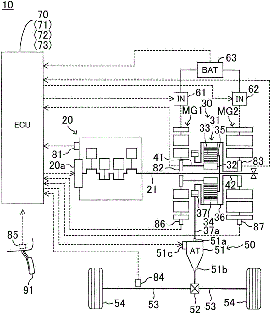
[0044] A control device (hereinafter, referred to as a first device) according to a first embodiment of the present invention is applied to a figure 1 The schematic configuration of the vehicle 10 is shown.

[0045] Vehicle 10 is a hybrid vehicle and includes a first electric motor (generator motor) MG1 , a second electric motor (generator motor) MG2 , and an engine 20 . The vehicle 10 further includes a power distribution mechanism 30 , a power transmission mechanism 50 , a first inverter 61 , a second inverter 62 , a battery 63 , and an electronic control unit (ECU) 70 .

[0046] The first motor MG1 and the second motor MG2 respectively include a stator including three-phase windings (coils) generating a rotating magnetic field, and a rotor including permanent magnets using the rotating magnetic field to generate torque through magnetic force.

[0047] Each of the first electric motor MG1 and the second electric motor MG2 is operable as a motor as well as a generator. Th...


PUM


Abstract

A control device is configured to: (i) control a rotation speed of an internal combustion engine (20) such that the rotation speed of the internal combustion engine is increased with an increase in a traveling speed of a vehicle (10), (ii) execute a pseudo gear shift to control the rotation speed of the internal combustion engine (20) such that the rotation speed of the internal combustion engine is decreased to a first rotation speed, (iii) execute a mechanical gear shift to change a second gear ratio according to a gear shift line determined by the traveling speed and a value according to the acceleration request, and (iv) execute adjustment control to adjust the rotation speed of the internal combustion engine in advance in a period before executing the mechanical gear shift such that the rotation speed of the internal combustion engine matches the pseudo gear shift threshold value when the mechanical gear shift is performed.

Description

technical field [0001] The invention relates to a control device for a vehicle comprising at least an internal combustion engine, a continuously variable transmission and a stepped transmission. Background technique [0002] A known hybrid vehicle includes a power split mechanism, and has an internal combustion engine (hereinafter, referred to as an engine), a first generator motor, a second generator motor, and a planetary gear mechanism. The planetary gears of the planetary gear mechanism are directly rotated by the engine through the planetary gear carrier. The sun gear of the planetary gear mechanism is directly rotated by the first generator motor. The ring gear of the planetary gear mechanism is directly rotated by the second generator motor through the ring carrier, and rotates the drive shaft of the vehicle. The rotation shaft of the spool (ie, the member that rotates the drive shaft of the vehicle) can be regarded as the output shaft of the power split mechanism. ...

Claims


Application Information

Patent Timeline
Patent Type & Authority Applications(China)
IPC IPC(8): B60W20/00B60W10/06B60W10/10
CPCB60W10/04F16H61/66F16H63/00B60W10/06B60W10/10B60W20/30B60W2710/0644B60W2710/1005B60K6/445B60K6/547B60W10/08B60W10/11B60W20/00B60W20/10B60W30/188B60W30/19B60W2520/10B60W2540/10B60W2710/0661B60W2710/1011F16H3/727F16H2037/023F16H2037/0866F16H2037/0873F16H2061/6615Y02T10/62Y10S903/918Y10S903/919Y10S903/93B60K6/36B60W10/101B60W10/111B60W2510/0638B60W2520/105
Inventor 池富和宽笹出晋一胜股宗弘椎葉一之松原亨北畑刚熊崎健太
Owner TOYOTA JIDOSHA KK
Learn More