
Testing device for hydrostatic pressure

A test device, hydrostatic pressure technology, applied in the direction of applying stable tension/pressure to test the strength of materials, etc., can solve the problems of affecting the service life of equipment, complicated installation of test pieces, and affecting test results, etc., to achieve safe, stable and sealed test process Excellent effect, convenient and reliable operation

Active Publication Date: 2016-03-30
CETC NINGBO MARINE ELECTRONICS RES INST
View PDF19 Cites 11 Cited by
  • Summary
  • Abstract
  • Description
  • Claims
  • Application Information

AI Technical Summary

Problems solved by technology

However, the test object is limited to cylindrical shells, and it cannot accurately simulate the real environment of water pressure; the other is hydraulic equipment with uniform pressure on the shell
This equipment can accurately simulate the real environment of water pressure, but all of the test pieces are under single external or internal pressure, which may easily cause the test piece to crack
Secondly, the installation of the test piece is relatively complicated, which affects the test results, and the size of the equipment is too large, which makes the operation and maintenance of the equipment very inconvenient
Furthermore, the end cover is generally tightened by bolts or locked by external torque, which is cumbersome to operate, and the end cover is easy to wear after long-term operation, which affects the service life of the equipment
The end cover is mostly sealed with a rubber gasket. Long-term extrusion will cause a decrease in sealing performance and pose a safety hazard.

Method used


Image

  • Testing device for hydrostatic pressure
  • Testing device for hydrostatic pressure
  • Testing device for hydrostatic pressure

Examples


Embodiment Construction

[0027] The present invention will be further described below in conjunction with the accompanying drawings.

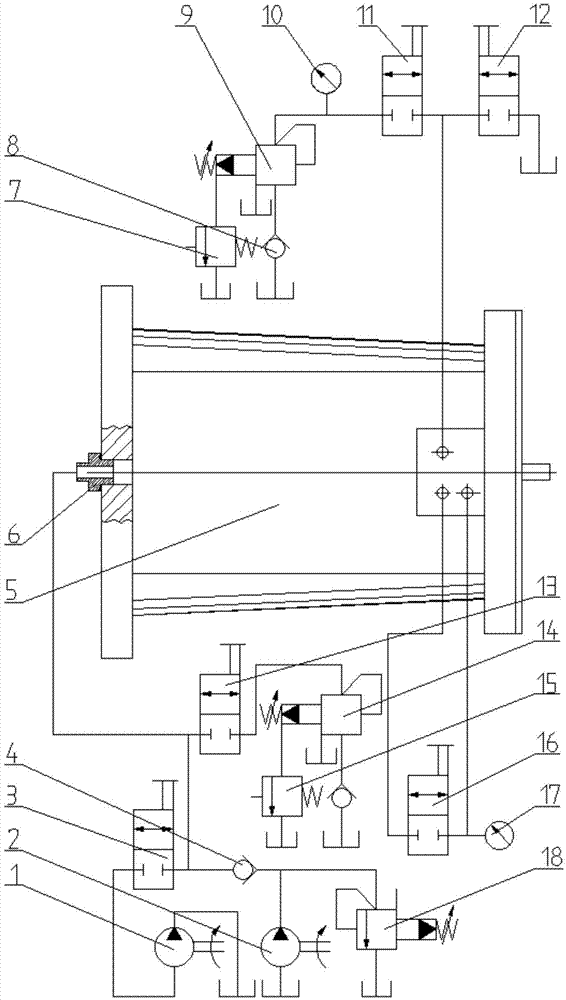
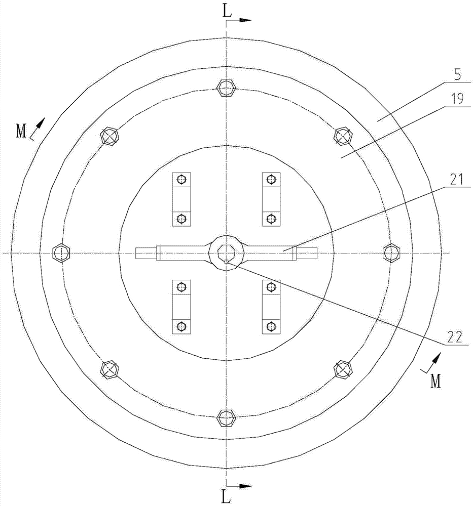
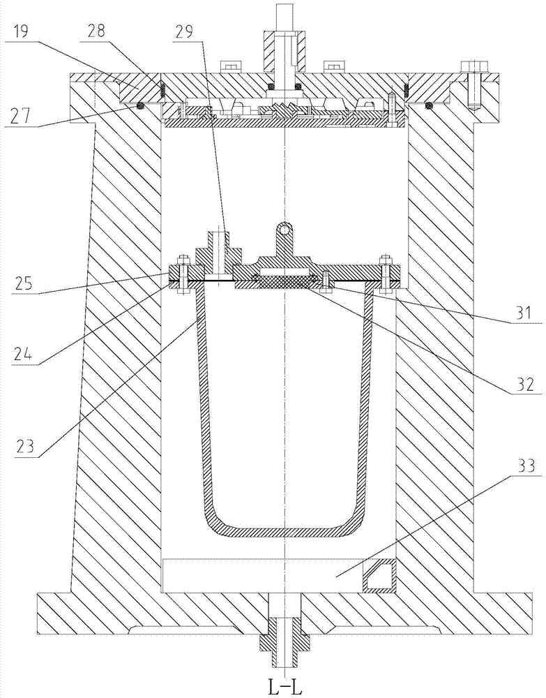
[0028] Such as Figure 1 to Figure 10 As shown, the hydrostatic pressure test device of the present invention comprises a high-pressure vessel shell 5 and a high-pressure vessel cover 38, the top of the high-pressure vessel shell 5 is provided with a high-pressure vessel cover frame 19, and the high-pressure vessel cover frame 19 is provided with a high-pressure vessel cover 38, A cover bottom plate 37 is installed below the high-pressure container cover 38, and a locking and sealing device sealing cover bottom plate 37 is installed on the high-pressure container cover 38. A sample device is placed in the high-pressure container housing 5, and a camera module 33 is arranged below the sample device. The bottom of the high-pressure container housing is connected with a water supply system through the high-pressure container water inlet connector 6; the sample device incl...


PUM


Abstract

The invention discloses a testing device for hydrostatic pressure. The testing device comprises a high pressure vessel shell and a high pressure vessel cover, wherein a high pressure vessel cover frame is arranged at the top of the high pressure vessel shell; the high pressure vessel cover is arranged in the high pressure vessel cover frame; a cover base plate is mounted under the high pressure vessel cover; a locking sealing device is arranged on the high pressure vessel cover and is used for sealing the cover base plate; a sample device is arranged in the high pressure vessel shell; a camera module is arranged under the sample device; a water supply system is connected with the bottom of the high pressure vessel shell; the sample device comprises a sample and a sample cover; quick couplers are mounted on the sample cover; a camera position external frame for fixing the camera is fixedly mounted under the sample cover; a transparent block is mounted at the center of the camera position external frame; two quick couplers are mounted on the sample cover. The testing device for hydrostatic pressure provided by the invention is characterized in that the port of a tested sample is connected with an end cover bolt and is embedded in the chamber of the high pressure vessel, the disassembling is convenient and quick, the replacement is benefited and the true environment of the hydrostatic pressure can be accurately simulated.

Description

technical field [0001] The invention relates to a hydrostatic pressure test device, which is suitable for pressure simulation inside and outside a pressure-resistant casing, and belongs to the field of marine equipment. Background technique [0002] Submersibles are important equipment for ocean exploration and deep-sea scientific research. As an important part of the submersible, the pressure-resistant shell plays a role in ensuring the normal operation of internal equipment and the health and safety of personnel during the dive process. The research and development design of the pressure body is very important. [0003] Existing pressure test equipment is mainly divided into two types: one is that the end is subjected to unidirectional pressure instead of uniformly distributed pressure on the shell. This equipment can avoid the sealing difficulty of water pressure, and uses mechanical extrusion, which is simple and reliable in action. However, the test object is limited ...

Claims


Application Information

Patent Timeline
IPC IPC(8): G01N3/12
CPCG01N3/12
Inventor 张建左新龙戴永健王明禄朱永梅唐文献相凯王纬波
Owner CETC NINGBO MARINE ELECTRONICS RES INST
Learn More