
Battery detection circuit

A battery detection and circuit technology, applied in the direction of measuring electricity, measuring devices, measuring electrical variables, etc., can solve problems such as burnout of field effect transistors

Active Publication Date: 2016-03-30
SHENXUN COMP KUNSHAN
View PDF9 Cites 5 Cited by
  • Summary
  • Abstract
  • Description
  • Claims
  • Application Information

AI Technical Summary

Problems solved by technology

[0005] Therefore, the purpose of the present invention is to provide a battery detection circuit to solve the problem that the field effect transistor on the protection circuit board is burned out due to the reverse connection of the positive and negative poles of the battery cell during assembly.

Method used


Image

  • Battery detection circuit
  • Battery detection circuit

Examples


Embodiment Construction

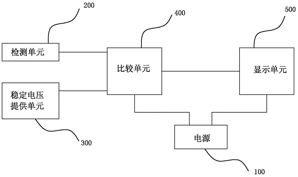
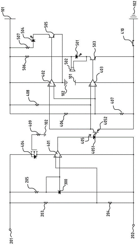
[0015] see figure 1 and figure 2 shown, where figure 1 A schematic block diagram of the battery detection circuit of the present invention is shown, figure 2 A circuit diagram of a preferred embodiment of the battery detection circuit of the present invention is shown.

[0016] In this embodiment, the battery detection circuit of the present invention includes: a power supply 100 , a detection unit 200 , a stable voltage supply unit 300 , a comparison unit 400 and a display unit 500 .

[0017] The power supply 100 has a positive pole 101 and a negative pole, and the negative pole is grounded 102 .

[0018] The detection unit 200 has a positive detection terminal 201 and a negative detection terminal 202, the positive detection terminal 201 is connected to the positive pole of the battery to be tested, the negative detection terminal 202 is connected to the negative pole of the battery to be tested, and the detection unit 200 It also includes a first resistor 203, a secon...


PUM


Abstract

A battery detection circuit includes: a power supply having a positive electrode and a negative electrode which is connected to the ground; a detection unit having a positive detection end and a negative detection end, wherein the positive detection end is connected with a positive electrode of a battery to be detected, and the negative detection end is connected with a negative electrode of a battery to be detected; a stable voltage providing unit which provides a stable voltage value; a comparison unit which is connected with the detection unit and the stable voltage providing unit and compares a voltage value of the detection unit with the stable voltage value of the stable voltage providing unit; and a display unit which is connected with the comparison unit and displays a result after comparison of the comparison unit. The battery detection circuit provided by the invention tests the voltage of the battery after assembling, then compares the voltage with the stable voltage value through the comparison unit, and displays the comparison result through the display unit, so as to judge whether the positive and negative electrodes are placed correctly when a battery core is assembled, thereby avoiding the problem that connection of positive and negative electrode of the battery core in reverse directions causes burnout of a field effect transistor on a circuit board.

Description

【Technical field】 [0001] The invention relates to a battery detection circuit, and in particular to a battery detection circuit capable of detecting whether the direction of the positive and negative poles of the batteries in the battery is reversed. 【Background technique】 [0002] With the development and progress of science and technology, electronic products are more and more widely used in homes and offices, and many electronic products use batteries as power supply devices. [0003] A battery is usually assembled by combining several groups of cells and then adding a protective circuit board, and a cell refers to a single electrochemical cell containing positive and negative electrodes, which is generally not used directly. If the positive and negative poles of one group of batteries are reversed when assembling the battery, when the whole battery is activated after welding the positive and negative poles of all the batteries, the external activation voltage power suppl...

Claims


Application Information

Patent Timeline
IPC IPC(8): G01R31/02
Inventor 许晶
Owner SHENXUN COMP KUNSHAN
Learn More