Reversible data hiding method and recovering method
A data hiding and recovery method technology, applied in the field of data hiding, can solve the problems of pixel redundancy, small embedding capacity, and insufficient utilization of multi-extreme value blocks.
Inactive Publication Date: 2016-03-30
NORTH CHINA ELECTRIC POWER UNIV (BAODING)
6 Cites 9 Cited by
AI-Extracted Technical Summary
Problems solved by technology
[0011] 3. Although each block can embed up to 2 bits of data, only the two ends of the gray value sequence are used, and the multi-extreme value ...
Method used
[0110] The above-mentioned process is illustrated with the k1 block, and the k2 block has a similar method and the same characteristics. It is not difficult to find that the second embedding method and the first embedding method of the present invention are carried out independently and do not affect each other, which greatly simplifies the complexity of data processing. Of course, at this time, part of the single-extre...
Abstract
The invention relates to a reversible data hiding method and a recovering method. The reversible data hiding method comprises a preprocessing step in which an original pixel-domain image is divided into blocks and the blocks are sorted according to the gray values, a marking step in which the sequence after sorting is detected and identified and feature-class blocks are marked, a watermark information embedding step in which watermark information is embedded into the feature-class blocks through a second embedding method, and an auxiliary information embedding step in which corresponding auxiliary information is embedded. According to the invention, on-demand watermark information embedding is realized, equal-maximum pixel redundancy in the image is fully exploited, 'one-position multi-bit embedding' is realized, and the information capacity is improved effectively. Meanwhile, seamless integration of a first embedding method and the second embedding method is achieved effectively.
Application Domain
Image data processing details
Technology Topic
Maximum PixelRestoration method +4
Image
Examples
- Experimental program(1)
Example Embodiment
[0079] The invention relates to the technical field of data hiding, in particular to a reversible data hiding method. Reversible data hiding technology refers to the embedding of watermark information into the carrier image during digital image processing. Authorized users can extract the watermark information from the embedded image and restore it to the original carrier image.
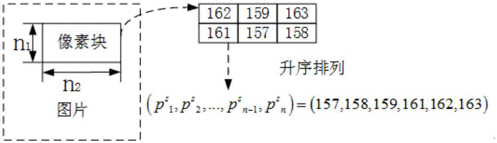
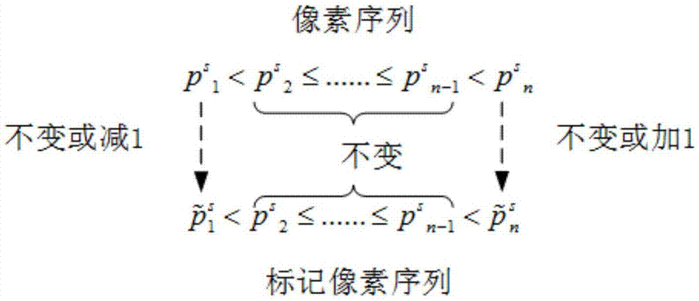
[0080] The inventive idea of the present invention is that after the image is divided into blocks, the pixel gray level in each block has a maximum value and a minimum value. For the entire original image, there may be many extreme values, including maximum values and minimum values. When using the first embedding method, only the single extreme pixels in the block are used. In order to make better use of the equal extremum pixels of the block to carry information bits, the present invention proposes a second embedding method. Specifically, the use of marker enhancement uses the sub-extreme pixels of the image, that is, the sub-maximum gray pixels and the sub-minimum gray pixels of the block, to predict the maximum gray pixels and the minimum gray pixels to form the sub-extreme pixel positions Figure. On this basis, the position map is used to mark the sub-maximum pixels in the image, and use it to predict the equal-maximum pixels in each block, realize the on-demand embedding of watermark information, and fully mine the equal-maximum pixels in the image Redundancy realizes "1 position, multi-bit embedding", which effectively improves the information capacity. At the same time, the seamless integration of the first embedding method and the second embedding method is effectively achieved.
[0081] Such as image 3 As shown, image 3 It is a brief flow chart of embedding watermark information in the reversible data hiding method of the present invention. The preprocessing steps include overflow block recognition and full smooth block recognition. The overflow block identification is mainly to establish an overflow pixel location map.
[0082] The following is mainly to identify the feature class block, and the identified feature class will be embedded in the watermark information according to the second embedding method. In analyzing the characteristic block, according to k 1 Class block, k 2 Class blocks and mixed k-class blocks are then embedded. If it is a non-characteristic class, the first embedding method is used to embed the watermark information. Therefore, the first embedding method and the second embedding method are seamlessly integrated, and the watermark information is flexibly embedded as needed.
[0083] Here, the term "watermark information" is information, which can form part of a coherent message, the encoder can embed it in the image and the decoder can then extract it from the image. Therefore, there is also an unencoded form of the watermark information before the watermark information is embedded in the image. Once embedded in the image, the watermark information can be restored completely and reversibly by adopting the decoder of the method according to one or more embodiments of the present invention.
[0084] The terms also used in the present invention are explained as follows:
[0085] Difference expansion: an expanded application that calculates the difference between two pixels and uses the difference to embed information.
[0086] Equal-maximum pixels: After the pixels in the image block are sorted by gray value, there are multiple pixels with the same size and the largest value.
[0087] Equal-maximum pixels: the maximum pixels in the image block, which are called equal-maximum pixels for the entire image.
[0088] Sub-maximum pixel: The pixels in the image block are sorted by gray value and the largest pixel smaller than the maximum value.
[0089] Sub-maximum pixel: The sub-maximum pixel in the image block, which is called the sub-maximum pixel for the entire image.
[0090] The above terminology and the technical solution of the present invention will be further described in detail through the following examples.
[0091] A reversible data hiding method includes a preprocessing step, an identification step, a watermark information embedding step, and an auxiliary information embedding step.
[0092] In the preprocessing step, the original pixel domain image is divided into blocks and sorted according to the gray value in the block.
[0093] The preprocessing steps include: block and sort. Blocking is to divide the original image into blocks of the same size but not overlapping each other. The original image is divided into blocks of the same size but not overlapping each other n 1 ×n 2 , And sort the pixels in the block in ascending order of gray value.
[0094] Sorting is to sort the pixels in the block according to the gray value. The pixels in this block are sorted by gray value in ascending or descending order.
[0095] The preprocessing step also includes overflow block recognition and full smooth block recognition. Among them, the overflow block identification is mainly to establish an overflow pixel location map, and adjust pixels 0 and 255 to 1 and 254 respectively. Fully smooth block recognition means that the gray values of all pixels in the block are the same, and a full smooth block position map is established. In the full-smooth recognition, the above-mentioned pixels (pixels 0 and 255) in the full-smooth block remain unchanged, and only the smooth block position map is used for identification. When encountering such blocks, no further analysis is needed, and the pixel value of the whole block remains unchanged.
[0096] The base pixel location map refers to when a specific block is encountered when scanning the block type, the sub-maximum base pixel and the sub-minimum base pixel are identified, and the base pixel location map is established, which is convenient for subsequent embedding, extraction and recovery links. Reversible operation of information.
[0097] For the above three location maps, if such a situation exists, it is marked as "1", otherwise it is marked as "0". After each location map is created, lossless compression is used to reduce its size.
[0098] In the identification step, the sorted sequence is detected, identified and the characteristic block is identified. This feature class block includes: k 1 Class block, k 2 Class blocks and mixed k-class blocks.
[0099] The number of pixels with the minimum gray value is 1, and the number of equivalent maximum gray values is 1 p-max ≤n-1, called k 1 Class block, where k 1 = N p-max , Denoted as
[0100] c(k 1 )=1 1 ≤n-1(5)
[0101] The number of pixels with the maximum gray value is 1, and the number of equivalent minimum gray values is 1 p-min ≤n-1, called k 2 Class block, where k 2 = N p-min , Denoted as
[0102] c(k 2 )=1 2 ≤n-1(6)
[0103] Number of pixels with equal maximum gray value 1 p-max ≤n-1, the number of equivalent minimum gray values 1 p-min ≤n-1, called mixed type k block, where k 1 = N p-max , K 2 = N p-min , And k 1 +k 2 ≤n-1, denoted as
[0104] c ( k 1 , k 2 ) = 1 k 1 ≤ n - 1 1 k 2 ≤ n - 1 k 1 + k 2 ≤ n - 1 - - - ( 7 )
[0105] The gray values of the block pixels are sorted in order of size, and the sub-maximum value is called the sub-maximum basis p s b-max , The corresponding pixel is called the sub-maximum base pixel p b-max; The second minimum is called the subminimum basis p s b-min , The corresponding pixel is called the sub-minimal base pixel p b-min.
[0106] In summary, in addition to equal gray value blocks, k 1 Only p in class block b-max , The gray value is k 2 Only p in class block b-min , The gray value is In the mixed k-type block and non-k-type block, there is already p b-max Also p b-min , And possibly p s b-max = P s b-min.
[0107] Such as Figure 4 As shown, Figure 4 It is a step diagram of embedding watermark information in the reversible data hiding method of the present invention. In this embodiment, only the case of equal maximum value embedding is analyzed. From Figure 4 It can be seen that the first block, Label k = 0, it means that this is not a type k block, and the traditional PVO embedding rules apply. Here, e max =163-162=1, information can be embedded at the maximum gray scale 163 pixels, where b=0, therefore, While e min =157-158=-1, information can be embedded at the smallest grayscale 157 pixels, here b=1, therefore,
[0108] The second, third, and fourth blocks, Means these are all k 1 For class blocks, the embedding rules of PVO-kAdaptive apply. In the second block, k 1 = 2, in P b-max Pixel location map Label k 1 = 1 , The size remains the same, while e k m a x = p s n - k 1 + 1 - p s n - k 1 = p s 5 - p s 4 = 162 - 161 = 1 , Therefore in eq(k 1 )={n-k 1 +1,n-k 1 +2,...,n} = pixels at positions such as {5,6} Embedded information bits, here b 5 = 0, b 6 = 1, execute p ~ e q ( k 1 ) s = p s e q ( k 1 ) + b , get p ~ 5 s = p s 5 + b = 162 + 0 = 162 , p ~ 6 s = p s 6 + b = 162 + 1 = 163. In the third block, k 1 = 2, in P b-max Pixel location map The size remains the same, while e k m a x = p s n - k 1 + 1 - p s n - k 1 = p s 5 - p s 4 = 162 - 160 = 2 1 , Therefore, eq(k 1 )={n-k 1 +1,n-k 1 +2,...,n} = pixels at positions such as {5,6} Shift right, execute p ~ e q ( k 1 ) s = p s e q ( k 1 ) + 1 , get p ~ 5 s = p s 5 + 1 = 162 + 1 = 163 , p ~ 6 s = p s 6 + 1 = 162 + 1 = 163. In block 4, k 1 = 4, in P b-max Pixel location map The size remains the same, while e k max = p s n - k 1 + 1 - p s n - k 1 = p s 3 - p s 2 = 160 - 159 = 1 , Therefore in eq(k 1 )={n-k 1 +1,n-k 1 +2,...,n} = pixels at positions such as {3,4,5,6} Embedded information bits, here b 3 = 0, b 4 = 1, b 5 = 1, b 6 =0, execute get p ~ 4 s = p s 4 + b = 160 + 1 = 161 , p ~ 5 s = p s 5 + b = 160 + 1 = 161 , p ~ 6 s = p s 6 + b = 160 + 0 = 160.
[0109] It should be noted that the 157 pixels in the second, third, and fourth sub-blocks remain unchanged regardless of the size of their neighboring pixels, which is different from the embedding conditions of the first embedding method. Therefore, the second embedding method runs in parallel with the first embedding method without interfering with each other.
[0110] The above process is based on k 1 As illustrated by the class block, k 2 The class block method is similar and has the same characteristics. It is not difficult to find that the second embedding method and the first embedding method of the present invention are performed independently and do not affect each other, which greatly simplifies the complexity of data processing. Of course, at this time, the uni-extreme pixels in part of the k-type blocks are sacrificed, and the first embedding method can be used to embed, but because it is judged to be a characteristic block, the information bits cannot be carried, and part of the embedding capacity is lost. In fact, because there is k> in the feature block 1-bit pixels are available and can be embedded sequentially, so the overall capacity is not reduced, but increased.
[0111] Judging from the average interference caused by the embedding of information bits, the mean square error of the k-type block is
[0112] MSE k = 1 n 1 X n 2 X i k = 1 n 1 X j k = 1 n 2 || I k ( i k , j k ) - I k e ( i k , j k ) || 2 = 1 n X i = 1 n ( p i - p i e ) 2 = 1 n ( X i = 1 k 2 ( p i - p i e ) 2 + X i = n - k 1 + 1 n ( p i - p i e ) 2 ) - - - ( 8 )
[0113] and
[0114] X i = 1 k 2 ( p i - p e i ) 2 = k 2 / 2 i f e k m i n = 1 k 2 i f e k m i n 1 - - - ( 9 )
[0115] X i = n - k 1 + 1 n ( p i - p e i ) 2 = k 1 / 2 i f e k max = 1 k 1 i f e k max 1 - - - ( 10 )
[0116] Thus, k 1 Embedded interference
[0117] MSE k 1 = k 1 / 2 n i f e k max = 1 k 1 / n i f e k max 1 - - - ( 11 )
[0118] k 2 Embedded interference
[0119] MSE k 2 = k 2 / 2 n i f e k m i n = 1 k 2 / n i f e k m i n 1 - - - ( 12 )
[0120] Embedded interference of mixed k-type blocks
[0121] MSE k h = ( k 1 + k 2 ) / 2 n i f e k max = 1 a n d e k min = 1 ( k 1 / 2 + k 2 ) / n i f e k max = 1 a n d e k min 1 ( k 1 + k 2 ) / 2 n i f e k max 1 a n d e k min = 1 ( k 1 + k 2 ) / n i f e k max 1 a n d e k min 1 - - - ( 13 )
[0122] As mentioned above, the flexibility and practicability of embedding have been greatly improved, so that each equivalent extreme value can carry information bits as needed, and the embedding quality has also been enhanced.
[0123] In the step of embedding the watermark information, the watermark information is embedded in the characteristic block by the second embedding method. The second embedding method in the step of embedding watermark information includes: determining the sub-maximum value: identifying the sub-maximum pixel position in the feature class block as 1, forming a sub-maximum pixel position map; calculating the prediction difference: calculating the feature class The difference between the maximum value and the sub-maximum value in the block; embedded watermark information: when the difference value is equal to 1, the binary code of the watermark data is superimposed on the multi-extremum sequence.
[0124] Specifically, identifying characteristic blocks, and embedding information according to the second embedding method. This feature class block includes: k 1 Class block, k 2 Class blocks and mixed k-class blocks. After finding the characteristic block, obtain the maximum and minimum size, number, and position of the sequence according to the gray value of the block pixels arranged in ascending order, as well as the size and sum of the sub-maximum and sub-minimum values. Position, embed information bits according to three types of blocks.
[0125] The first type of block is k 1 Class block. Only a few pixels with maximum values may be modified. Mark i∈{1,2,...,n}, e k m a x = p s n - k 1 + 1 - p s n - k 1 , Then there is
[0126] p ~ i s = p s i i f 1 ≤ i ≤ n - k 1 p s i + b i f n - k 1 + 1 ≤ i ≤ n a n d e k max = 1 p s i + 1 i f n - k 1 + 1 ≤ i ≤ n a n d e k max 1 - - - ( 14 )
[0127] Here, e k max Is the maximum prediction error, b∈{0,1} is the information bit to be embedded. Obviously, information embedding is performed only when the maximum prediction error is 1.
[0128] The second type of block is k 2 Class block. Only a few minimal pixels may be modified. Mark i∈{1,2,...,n}, e k min = p s k 2 - p s k 2 + 1 , Then there is
[0129] p ~ i s = p s i i f k 2 + 1 ≤ i ≤ n p s i - b i f 1 ≤ i ≤ k 2 a n d e k min = - 1 p s i - 1 i f 1 ≤ i ≤ k 2 a n d e k min - 1 - - - ( 15 )
[0130] Here, e k min Is the minimum prediction error, b∈{0,1} is the information bit to be embedded. Obviously, information embedding is performed only when the minimum prediction error is 1.
[0131] The third type of block is a mixed type k block. Some pixels with maximum values may be modified, and pixels with minimum values may be modified. Mark i∈{1,2,...,n}, e k max And e k min Respectively and k 1 Class block and k 2 The class block is the same, there are
[0132] p ~ i s = p s i i f k 2 + 1 ≤ i ≤ n - k 1 p s i + b i f n - k 1 + 1 ≤ i ≤ n a n d e k max = 1 p s i + 1 i f n - k 1 + 1 ≤ i ≤ n a n d e k max 1 p s i - b i f 1 ≤ i ≤ k 2 a n d e k min = - 1 p s i - 1 i f 1 ≤ i ≤ k 2 a n d e k min - 1 - - - ( 16 )
[0133] Here, b∈{0,1} is the information bit to be embedded. Obviously, information embedding is performed only when the maximum value error is 1 and the minimum value prediction error is -1.
[0134] In the step of embedding auxiliary information, corresponding auxiliary information is embedded. The step of embedding auxiliary information includes: replacing the least significant bit: calculating the length of the auxiliary information, extracting the least significant bit of the same number of pixels in the image as the auxiliary information, and replacing it with auxiliary information; embedding the least significant bit: the lowest extracted The valid bit sequence is embedded in the pixel after the data is finally embedded in the block.
[0135] The auxiliary information in the step of embedding auxiliary information includes: a location map and an auxiliary information identifier. The position map in the step of embedding auxiliary information includes an overflow pixel position map, a fully smooth block position map, and a base pixel position map. The auxiliary information identifier in the step of embedding auxiliary information includes payload capacity, block size, compressed location map size, last embedded block index, and last embedded pixel index.
[0136] Specifically, the auxiliary information mainly refers to the embedding capacity, the block size, the overflow pixel location map and the final embedding block index. The special auxiliary information for the feature block includes the full smooth block location map, the base pixel location map and the last embedded pixel index.
[0137] In summary, the total embedded information can be identified as watermark payload (PWP) + location map (LM) + auxiliary information identification (All), where the location map includes the overflow pixel location map, the full smooth block location map and the base pixel location Figure; For an image with an image size of 512*512, the auxiliary information identifier (All) has 112 bits, including
[0138] Payload capacity (18bits)
[0139] Block size n1*n2(4bits)
[0140] Compressed position map size 54bits
[0141] Finally embed the block index (18bits)
[0142] Finally embedded pixel index (18bits)
[0143] The present invention is compared with the first embedding method and the two prior art methods. Using MatlabR2013a platform, 64-bit Windows7 flagship operating system, Intel(R)Core(TM)i7-2600CPU, clocked at 3.40Hz, memory 4.00GB environment for fixed load embedded experiment simulation. Consider n 1 ,n 2 ∈{2,3,4,5}, etc., there are 16 different block methods, and the block size is determined with the goal of fidelity improvement to obtain the highest PSNR value.
[0144] To facilitate the comparison, the present invention selects the same test pictures, which mainly include the comparison results of eight standard grayscale pictures with 512*512 resolution of Lena, Baboon, Airplane, Barbara, Elaine, Lake, Boat and Peppers. The method of the present invention mainly embeds information bits by modifying at most 1 unit of the gray value of a certain pixel, and strives to improve the embedding quality. Here, the PSNR value from 5000bits to the maximum embedding capacity is compared, and the step size is set to 1000bits. The maximum embedding capacity of the eight images is 37000, 13000, 47000, 21000, 23000, 26000, 26000 and 31000 bits in order.
[0145] As shown in Fig. 5, Fig. 5 is a comparison diagram of the reversible data hiding method of the present invention and the other three methods, in which, Figure 5a The comparison chart of Lena picture as an example, 5b is the comparison chart of Baboon picture as an example, 5c is the comparison chart of Airplane picture as an example, 5d is the comparison chart of Barbara picture as an example, 5e is the comparison chart of Elaine picture as an example, 5f Take the picture of Lake as an example of comparison chart, Figure 5g Take the Boat picture as an example of comparison chart, Figure 5h Take the picture of Peppers as an example for comparison. The first comparison method in the picture is referred to as "Sachnevetal". The second comparison method is referred to as "Lietal.", which is the first embedding method. The third comparison method is referred to as Ouetal.). The present invention is referred to as "Proposed" for short.
[0146] It can be seen from Figure 5 that compared with the third comparison method, the performance of the two is relatively close. At the low embedding rate of Lena and Airplane, the performance is lower, but the medium and high embedding rate is significantly improved. This is because at the low embedding rate, the third comparison method uses a threshold optimization strategy, while this method is The large proportion of the location map causes high interference; in the Baboon and Barbara images, the performance is slightly lower. This is because the texture level of the two images is complex, and the third comparison method performs the overall embedding and matches the threshold selection strategy . The performance of the four pictures of Elaine, Lake, Boat and Peppers has improved a lot, which shows that this method has better fidelity performance in medium and high embedding rate applications. Referring to Table 1 and Table 2, the method of the present invention has an average increase of 0.66 dB corresponding to 10,000 bits of embedding compared to the method of the third comparison method, and an increase of 1.13 dB corresponding to 20,000 bits of embedding.
[0147] Table 1
[0148]
[0149] Table 2
[0150]
[0151] It can be seen from Table 1 and Table 2 above that the method proposed in the present invention can obtain a higher PSNR value in most cases of a given embedding load.
[0152] Compared with the first comparison method, the method proposed by the present invention achieves better performance in most situations, but the performance is comparable when approaching the maximum capacity. Referring to Table 1 and Table 2, the method of the present invention has an average increase of 2.91 dB corresponding to 10,000 bits of embedding compared to the method of the first comparison method, and an increase of 2.73 dB corresponding to 20,000 bits of embedding.
[0153] In comparison, corresponding to all test pictures, the method proposed in the present invention has achieved better performance. Referring to Table 1 and Table 2, the method of the present invention has an average increase of 1.53 dB corresponding to 10,000 bits of embedding compared to the method of the second comparison method, and an increase of 2.02 dB corresponding to 20,000 bits of embedding.
[0154] In general, the method of the present invention has achieved good performance, and the embedding flexibility and practicability have been greatly improved, so that each equivalent extreme value can carry information bits as required, and the embedding quality is also enhanced.
[0155] The invention also provides a method for information extraction and image restoration. Since the present invention effectively achieves the seamless fusion of the first embedding method and the second embedding method, the first embedding method and the second embedding method are performed independently when recovering, and it is found that there are image parts using the first embedding method. The extraction and image restoration using the first embedding method are not described here because it is the prior art. The process of information extraction and image restoration using the second embedding method in the discovery of characteristic blocks.
[0156] Specifically, the characteristic class block includes: k 1 Class block, k 2 The class block and mixed k class block are restored according to the different class blocks.
[0157] When k is recognized 1 Class block, in this case, The extracted information bits are
[0158] b = p ~ i s - ( p s n - k 1 + 1 ) - - - ( 17 )
[0159] The image restoration strategy is,
[0160] p s i = p ~ i s i f 1 ≤ i ≤ n - k 1 p ~ i s - b i f n - k 1 + 1 ≤ i ≤ n a n d e ~ max k A { 1 , 2 } p ~ i s - 1 i f n - k 1 + 1 ≤ i ≤ n a n d e ~ max k 2 - - - ( 18 )
[0161] Here, Is the maximum prediction error. Obviously, for the pixel with embedded information bit, the information bit b extracted by formula [17] is based on the submaximal basis p s b-max As a basis to measure, so the restored image gray value is
[0162] p s i = p ~ i s - b = p ~ i s - ( p ~ i s - ( p s n - k 1 + 1 ) ) = p s n - k 1 + 1 - - - ( 19 )
[0163] In other words, the restored image gray value is completely determined by the submaximal basis p s b-max To decide. and with Then b=0 and b=1 are respectively identified.
[0164] When set k 2 Class block, in this case, The extracted information bits are
[0165] b = ( p s k 2 - 1 ) - p ~ i s - - - ( 20 )
[0166] The image restoration strategy is,
[0167] p s i = p ~ i s i f k 2 + 1 ≤ i ≤ n p ~ i s + b i f 1 ≤ i ≤ k 2 a n d e ~ min k A { - 1 , - 2 } p ~ i s + 1 i f 1 ≤ i ≤ k 2 a n d e ~ min k - 2 - - - ( twenty one )
[0168] Here, It is the minimum prediction error. Obviously, for the pixel with embedded information bit, the information bit b extracted by formula [20] is the sub-minimal basis p s b-max As a basis to measure, so the restored image gray value is
[0169] p s i = p ~ i s + b = p ~ i s + ( ( p s k 2 - 1 ) - p ~ i s ) = p s k 2 - 1 - - - ( twenty two )
[0170] In other words, the gray value of the restored image is completely determined by the sub-minimum basis p s b-min To decide. and with Then b=0 and b=1 are respectively identified.
[0171] When a mixed type k block is identified, in this case, i A { 1 , 2 , ... , n } , e ~ m a x k = p ~ n - k 1 + 1 s - p s n - k 1 , e ~ min k = p ~ k 2 s - p s k 2 + 1 , The information bits extracted at the equivalent maximum are
[0172] b 1 = p ~ i s - ( p s n - k 1 + 1 ) - - - ( twenty three )
[0173] The information bits extracted at the equivalent minimum are
[0174] b 2 = ( p s k 2 - 1 ) - p ~ i s - - - ( twenty four )
[0175] The image restoration strategy is,
[0176] p s i = p ~ i s i f k 2 + 1 ≤ i ≤ n - k 1 p ~ i s - b 1 i f n - k 1 + 1 ≤ i ≤ n a n d e ~ max k A { 1 , 2 } p ~ i s - 1 i f n - k 1 + 1 ≤ i ≤ n a n d e ~ max k 2 p ~ i s + b 2 i f 1 ≤ i ≤ k 2 a n d e ~ min k A { - 1 , - 2 } p ~ i s + 1 i f 1 ≤ i ≤ k 2 a n d e ~ min k - 2 - - - ( 25 )
[0177] Here, with These are the prediction errors of the maximum and minimum values respectively. Obviously, for the pixel with embedded information bit, the information bit b extracted by formula [23] 1 Is the submaximal basis p s b-max As a basis to measure, so the restored image gray value is
[0178] p s i = p ~ i s - b = p ~ i s - ( p ~ i s - ( p s n - k 1 + 1 ) ) = p s n - k 1 + 1 - - - ( 26 )
[0179] In other words, the restored image gray value is completely determined by the submaximal basis p s b-max To decide. and with Then b=0 and b=1 are respectively identified.
[0180] Use formula [23] to extract information bits b 2 Is the smallest base p s b-min As a basis to measure, so the restored image gray value is
[0181] p s i = p ~ i s + b 2 = p ~ i s + ( ( p s k 2 - 1 ) - p ~ i s ) = p s k 2 - 1 - - - ( 27 )
[0182] In other words, the gray value of the restored image is completely determined by the sub-minimum basis p s b-min To decide. and with Then b=0 and b=1 are respectively identified.
[0183] The invention can also be implemented on systems such as windows and Linux. The embodiments of the present invention are described with reference to the flowcharts and/or block diagrams of the methods, terminal devices (systems), and computer program products according to the embodiments of the present invention. It should be understood that each process and/or block in the flowchart and/or block diagram, and the combination of processes and/or blocks in the flowchart and/or block diagram can be implemented by computer program instructions. These computer program instructions can be provided to the processors of general-purpose computers, special-purpose computers, embedded processors, or other programmable data processing terminal equipment to generate a machine, so that instructions executed by the processor of the computer or other programmable data processing terminal equipment Generated for implementation in the process Figure one Process or multiple processes and/or boxes Figure one A device with functions specified in a block or multiple blocks.
[0184] Such computer program instructions can also be stored in a computer-readable memory that can guide a computer or other programmable data processing terminal equipment to work in a specific manner, so that the instructions stored in the computer-readable memory produce an article of manufacture including the instruction device, The instruction device is implemented in the process Figure one Process or multiple processes and/or boxes Figure one Functions specified in a box or multiple boxes.
[0185] Such computer program instructions can also be loaded on a computer or other programmable data processing terminal equipment, so that a series of operation steps are executed on the computer or other programmable terminal equipment to generate computer-implemented processing, so that the computer or other programmable terminal The instructions executed on the device are provided for Figure one Process or multiple processes and/or boxes Figure one Steps of functions specified in a box or multiple boxes.
[0186] Although the preferred embodiments of the embodiments of the present invention have been described, those skilled in the art can make additional changes and modifications to these embodiments once they learn the basic creative concept. Therefore, the appended claims are intended to be interpreted as including the preferred embodiments and all changes and modifications falling within the scope of the embodiments of the present invention.
[0187] Finally, it should be noted that in this article, relational terms such as first and second are only used to distinguish one entity or operation from another entity or operation, and do not necessarily require or imply these entities Or there is any such actual relationship or sequence between operations. Moreover, the terms "include", "include" or any other variants thereof are intended to cover non-exclusive inclusion, so that a process, method, article or terminal device including a series of elements not only includes those elements, but also includes those that are not explicitly listed. Other elements listed, or also include elements inherent to this process, method, article or terminal device. If there are no more restrictions, the element defined by the sentence "including a..." does not exclude the existence of other same elements in the process, method, article or terminal device that includes the element.
[0188] The synchronization method and synchronization system provided by the embodiments of the present invention are described in detail above. Specific examples are used in this article to explain the principles and implementation manners of the embodiments of the present invention. The description of the above embodiments is only for help Understand the methods and core ideas of the embodiments of the present invention; at the same time, for those of ordinary skill in the art, according to the ideas of the embodiments of the present invention, there will be changes in the specific implementation and scope of application. In summary, The content of this specification should not be construed as a limitation to the embodiments of the present invention.
PUM


Description & Claims & Application Information
We can also present the details of the Description, Claims and Application information to help users get a comprehensive understanding of the technical details of the patent, such as background art, summary of invention, brief description of drawings, description of embodiments, and other original content. On the other hand, users can also determine the specific scope of protection of the technology through the list of claims; as well as understand the changes in the life cycle of the technology with the presentation of the patent timeline. Login to view more.