Histogram data collector for applying progressively adjusted histogram equalization to an oscilloscope image

a technology of oscilloscope and data collector, which is applied in the field of oscilloscope employing and displaying histograms, can solve the problem that the mapping function generated from the output image may not precisely equalize the histogram, and achieve the effect of easy detection of the difference in intensities

Active Publication Date: 2006-11-21
TEKTRONIX INC
View PDF8 Cites 14 Cited by
  • Summary
  • Abstract
  • Description
  • Claims
  • Application Information

AI Technical Summary

Benefits of technology

[0009]The present invention addresses the problem of applying histogram equalization to an oscilloscope waveform display. The dynamic range of display intensities is more full

Problems solved by technology

Since a histogram of the output image cannot fully represent all the information of a histogram of the in

Method used


Image

  • Histogram data collector for applying progressively adjusted histogram equalization to an oscilloscope image
  • Histogram data collector for applying progressively adjusted histogram equalization to an oscilloscope image
  • Histogram data collector for applying progressively adjusted histogram equalization to an oscilloscope image

Examples


Embodiment Construction

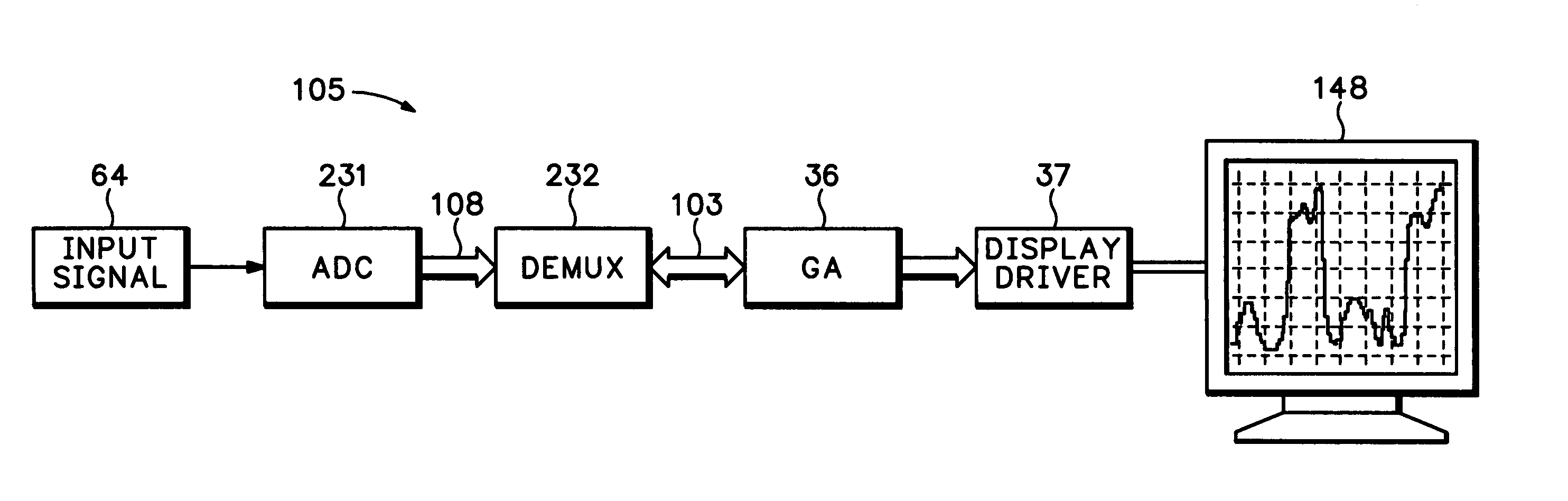
[0031]Referring to FIG. 5, a first embodiment of the present invention begins with a rasterized input image 64 which is processed by an image mapper 61, the mapper typically reducing the number of bits per pixel from 32 to 8 (or less). The mapper 61 converts or transfers the N bits / pixel of intensity appearing in the input rasterized image 64 to the lesser n bits / pixel that are available for display in the output image 148. The mapped raster image 148 is forwarded to a histogram collector 110 and the intensity levels of that image are processed by computer program 150 in order to equalize the pixel distribution within image. In this primarily software implementation of the invention, the histogram collector 110 is composed primarily of memory along with a suitable microprocessor for interacting with the computer program 150.

[0032]Referring also to FIG. 6, the program 150 begins at step 40 by collecting the output raster image 148 intensity data. At step 41, the maximum intensity I p...


PUM


Abstract

A system is disclosed for equalizing the distribution of pixel intensities in an image displayed by an oscilloscope. In a primarily software implementation, the maximum pixel intensity (I) present in the rasterized input image, the maximum available display intensity (P) and the desired image resolution (R) are the input variables which permit the calculation of thresholds or bins to which each pixel is assigned. By iteratively performing the analysis of existing pixel intensities and bin thresholds, the number of pixels in each bin may be optimized to form an equalized histogram. Another implementation of the histogram equalization system utilizes software to optimize a hardware-based histogram collector.

Description

CLAIM OF PRIORITY[0001]This application is based on and claims priority from U.S. Provisional Application Ser. No. 60 / 356,883, filed on Feb. 12, 2002.FIELD OF THE INVENTION[0002]The subject invention relates generally to the field of oscilloscope display systems, and more particularly to an oscilloscope employing and displaying histograms.BACKGROUND OF THE INVENTION[0003]Current oscilloscopes can display images of waveforms derived from an internal image which may possess a large dynamic range of pixel intensities. Although the variation in pixel intensity of the internal image may be large, the actual display of this image limits the intensity range and therefore does not fully reflect all of the information contained in the internal image. An example of an oscilloscope which illustrates this problem is disclosed in U.S. Pat. No. 5,986,637 entitled DIGITAL OSCILLOSCOPE ARCHITECTURE FOR SIGNAL MONITORING WITH ENHANCED DUTY CYCLE, issued to Etheridge et al. The Etheridge et al. devic...

Claims


Application Information

Patent Timeline
IPC IPC(8): G06K9/00G01R13/20G06T5/40
CPCG01R13/0218G06T5/009G06T5/40
Inventor IVERS, KEVIN T.GERLACH, PAUL M.TAYLOR, DANIEL E.
Owner TEKTRONIX INC
Why Eureka
Try Eureka