
Radial multi-coil parallel magnetic circuit multi-adhesion surface high-speed electromagnet

A technology of high-speed electromagnet and suction surface, applied in the field of electromagnet, can solve the problems affecting the safety, reliability and life of the electromagnet, the increase of current rising speed and decay speed, affecting the dynamic response characteristics of the electromagnet, etc., to achieve good magnetic permeability energy, reduce power consumption, and evenly distribute the magnetic induction intensity

Active Publication Date: 2017-08-04
HARBIN ENG UNIV
View PDF5 Cites 0 Cited by
  • Summary
  • Abstract
  • Description
  • Claims
  • Application Information

AI Technical Summary

Problems solved by technology

[0003] The traditional "E" type high-speed electromagnet is often driven by a large current and maintained by a small current. The electromagnet is magnetized repeatedly, which makes the hysteresis loss and eddy current loss serious.
In addition, the large current drive and small current maintenance for the large pulse width working state, the current action time is long, resulting in increased heat generation of the coil, affecting the safety reliability and life of the electromagnet; single coil multi-turn winding method also makes the coil The inductance of the electromagnet is large, resulting in an increase in the current rising speed and decay speed, which affects the dynamic response characteristics of the electromagnet

Method used


Image

  • Radial multi-coil parallel magnetic circuit multi-adhesion surface high-speed electromagnet
  • Radial multi-coil parallel magnetic circuit multi-adhesion surface high-speed electromagnet
  • Radial multi-coil parallel magnetic circuit multi-adhesion surface high-speed electromagnet

Examples


Embodiment Construction

[0024] The present invention will be described in more detail below with examples in conjunction with the accompanying drawings.

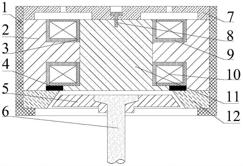
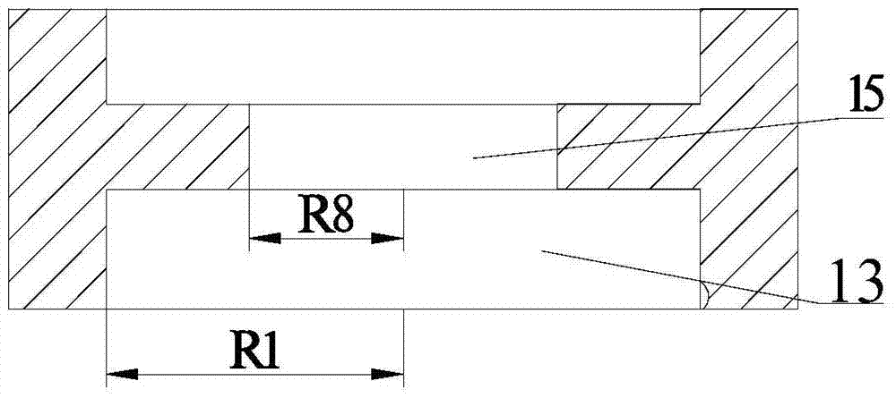
[0025] combine figure 1 , figure 2 , Figure 3(a), Figure 3(b), Figure 4 , Figure 5(a), Figure 5(b), Image 6 with Figure 7 , the composition of radial multi-coil parallel magnetic circuit multi-adhesion surface high-speed electromagnet of the present invention comprises housing 1, outer iron core 2, sealing resin 3, permanent magnet 4, armature 5, valve stem 6, fastening nut 7, Screw 8, bobbin 9, coil 10, inner core 11 and yoke 12. The housing 1 is a cylinder with a stepped through hole in the center, and the upper end is tapped with threads, and a fastening screw 7 is provided. The screw 7 has a countersunk hole 14 in the center, and an annular groove 23 at the bottom, and a cylindrical structure with a through hole 24 in the center of the groove; the outer iron core 2 has grooves 13 at both ends, and a groove in the center The cylinder o...


PUM


Abstract

The invention provides a radial multi-coil parallel magnetic circuit multi-adhesion high-speed electromagnet. It includes an outer shell, iron core, yoke, armature and coil, and also includes a permanent magnet. The iron core is composed of an inner iron core and an outer iron core. The permanent magnet is a cylindrical ring concentric with the iron core. The inner iron core or the outer iron The bottom of the core protrudes from the flange, and the permanent magnet is embedded between the flange and another iron core. The upper surface of the permanent magnet is flush with the upper surface of the flange, and the lower surface is flush with or slightly lower than the lower surface of the iron core. The magnetization direction is radial radiation magnetization; the yoke is a cylinder with a tapered through hole in the center, and the end of the tapered through hole with a small radius is close to the lower end of the outer iron core. The armature is conical, and the cone of the armature The angle is equal to the taper angle of the yoke taper through hole. The invention has the characteristics of strong electromagnetic force, fast response and low driving current, and is suitable for the electric control fuel system of the diesel engine.

Description

technical field [0001] The invention relates to an electromagnet, in particular to a high-speed electromagnet for an electronically controlled fuel system of a diesel engine. Background technique [0002] The electronically controlled fuel injection system of diesel engine has the characteristics of high injection pressure, flexible and controllable fuel injection timing and injection law, and is an important means to improve the performance of diesel engine fuel system at present. In recent years, the electronic control of the diesel fuel system has been vigorously developed, and the electronically controlled fuel injection system has become an important technology to meet the increasingly stringent emission regulations and improve the economy of diesel engines. An electromagnet whose response speed can reach milliseconds can be called a high-speed electromagnet. The high-speed powerful electromagnet is a key component in the electronically controlled fuel injection system...

Claims


Application Information

Patent Timeline
Patent Type & Authority Patents(China)
IPC IPC(8): H01F7/08H01F7/122F02M51/00
Inventor 范立云刘鹏马修真李文辉周伟董全
Owner HARBIN ENG UNIV
Learn More