A surface-layer rolled carbon fiber film colloidal battery plate and its production and preparation method

A colloidal battery, carbon fiber membrane technology, applied in lead-acid battery electrodes, battery electrodes, circuits, etc., can solve the problems of uneven negative vulcanization degree, increased battery water loss rate, large grid corrosion rate, etc., and achieve excellent corrosion resistance. performance and high current discharge capability, reducing impedance and improving cycle life

Active Publication Date: 2018-12-07
JIANGSU OLITER ENERGY TECH
View PDF6 Cites 0 Cited by
  • Summary
  • Abstract
  • Description
  • Claims
  • Application Information

AI Technical Summary

Problems solved by technology

At present, the uneven distribution of carbon materials in traditional lead-carbon batteries will lead to uneven vulcanization of the negative electrode. The disadvantages are large ohmic resistance, high gas evolution rate, and increased battery water loss rate.
The corrosion rate of the grid is greater when the ring is used, and the battery capacity will drop significantly as the battery cycles later in the cycle

Method used


Image

  • A surface-layer rolled carbon fiber film colloidal battery plate and its production and preparation method
  • A surface-layer rolled carbon fiber film colloidal battery plate and its production and preparation method

Examples


Embodiment 1

[0019] In this embodiment, the lead alloy coated with lead paste is used as the substrate. After coating, the surface is pressed into a 0.03mm uneven shape with a precision balance hydraulic press, and a layer of PTFE adhesive is sprayed with a spray gun.

[0020] The specific PTFE binder parameters are as follows: 40g / L tetrafluoroethylene, 12g / L polypropylene, 13g / L potassium sulfate, and 1.8g / L silicon dioxide are completely mixed and dissolved, and then fully stirred , at a distance of 10MM from the plate, spray 3 to 10 microns.

[0021] The remaining components of the carbon fiber membrane are 50g of modified activated carbon, 2g of graphene, and 12g of magnesium oxide, mixed together, ground evenly, coated on a PTFE adhesive plate, rolled by a precision balanced hydraulic machine, and dried at 60 degrees. The surface layer is mainly composed of lead and contains about 12% metallic carbon, 0.8% fiber and trace amounts of organic matter.

Embodiment 2

[0023] In this embodiment, the lead alloy coated with lead paste is used as the matrix. After coating, the surface is pressed into a 0.04mm uneven shape with a precision balance hydraulic press, and a layer of PTFE adhesive is sprayed with a spray gun.

[0024] The specific PTFE binder parameters are as follows: 40g / L tetrafluoroethylene, 12g / L polypropylene, 13g / L potassium sulfate, and 1.8g / L silicon dioxide are completely mixed and dissolved, and then fully stirred , at a distance of 10MM from the plate, spray 3 to 10 microns.

[0025] The remaining components of the carbon fiber membrane are 50g of modified activated carbon, 6g of graphene, and 10g of magnesium oxide, mixed together, ground evenly, coated on a PTFE adhesive plate, rolled by a precision balanced hydraulic press, and dried at 60 degrees. The surface layer is mainly composed of lead and contains about 11% metallic carbon, 0.8% fiber and trace amounts of organic matter.


PUM

PropertyMeasurementUnit
thicknessaaaaaaaaaa
particle diameteraaaaaaaaaa
electrical conductivityaaaaaaaaaa

Abstract

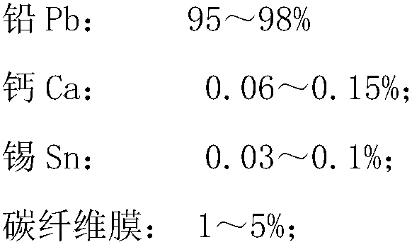
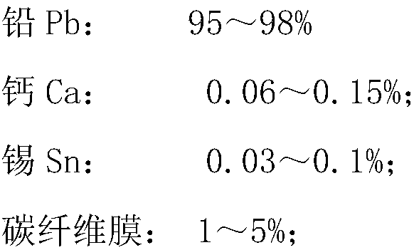
The invention discloses a storage battery electrode plate with carbon fiber membrane colloid laminated on a surface layer and a preparation method. A positive electrode plate comprises a substrate and the surface layer, wherein the surface layer is formed in a laminating manner and mainly comprises the following components in percentage by mass: 95%-98% of lead (Pb), 0.06%-0.15% of calcium (CA), 0.03%-0.1% of stannum (Sn) and 1%-5% of a carbon fiber; and a carbon fiber membrane is prepared from the following components by mass fraction: 52%-67% of carbon (C), 12%-22% of graphene, 8%-21% of a PTFE binder and the balance being inevitable impurities. The electrode plate disclosed by the invention has relatively high heavy current discharge performance and relatively high hydrogen-evolution and oxygen-evolution over-potential, so that a storage battery electrolyte is relatively stable and free of maintenance.

Description

technical field [0001] The invention belongs to the technical field of lead-acid batteries, in particular to the technology of lead-carbon batteries. Background technique [0002] As the power source of new energy electric vehicles, lead-acid batteries are being used more and more because of their excellent charge and discharge performance and long life. At present, activated carbon components are introduced into the lead-acid battery plates to form the characteristics of supercapacitors. Can greatly improve the performance of lead-carbon batteries. At present, the uneven distribution of carbon materials in traditional lead-carbon batteries will lead to uneven vulcanization of the negative electrode. The disadvantages are large ohmic resistance, high gas evolution rate, and increased battery water loss rate. The corrosion rate of the grid is greater when the ring is used, and the battery capacity will drop significantly with the later stages of the battery cycle. Contents...

Claims


Application Information

Patent Timeline
Patent Type & Authority Patents(China)
IPC IPC(8): H01M4/583H01M4/14H01M4/16
CPCH01M4/14H01M4/16H01M4/583Y02E60/10
Inventor 许文勇谭乃云袁朝勇严学庆王双印赵荣兴王发明黄桂宝
Owner JIANGSU OLITER ENERGY TECH
Why Eureka
Try Eureka