SOE time synchronization control method and system

A time synchronization and control method technology, which is applied in the direction of time division multiplexing system, electrical components, multiplexing communication, etc., can solve the problems of increasing system cost, SOE accuracy is difficult to reach 1ms, etc., so as to improve the accuracy of time synchronization , to achieve the effect of cost and precision, low cost

Active Publication Date: 2016-03-30
HANGZHOU HOLLYSYS AUTOMATION
View PDF3 Cites 24 Cited by
  • Summary
  • Abstract
  • Description
  • Claims
  • Application Information

AI Technical Summary

Problems solved by technology

Since the NTP time synchronization accuracy can only reach the 10ms level, it is difficult for the SOE accuracy between different control stations to reach 1ms
[0006] Method 2: Use the IEEE1588 protocol (PTP) between controllers to achieve time synchronization with 10us accuracy. Other time synchronization mechanisms are similar to metho...

Method used


Image

  • SOE time synchronization control method and system
  • SOE time synchronization control method and system
  • SOE time synchronization control method and system

Examples


Embodiment 1

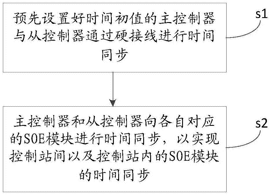
[0064] Please refer to figure 1 , figure 1 It is a flowchart of the process of a SOE time synchronization control method provided by the present invention;

[0065] This method is applied to the SOE time synchronization control system. Each controller corresponds to a control station. The controller of one control station is selected as the master controller for time synchronization. The controllers of the remaining control stations are slave controllers. The controller and the slave controller are connected by hard wiring. The method includes:

[0066] Step s1: The master controller and the slave controller with the preset time initial value are time synchronized through hard wiring;

[0067] Step s2: The master controller and the slave controller perform time synchronization to their corresponding SOE modules to achieve time synchronization between the control stations and the SOE modules in the control stations.

[0068] It is understandable that the operator can limit the master-s...

Embodiment 2

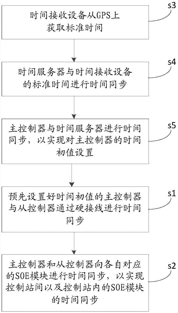
[0073] Please refer to image 3 , image 3 It is a flowchart of another SOE time synchronization control method provided by the present invention.

[0074] The method includes:

[0075] Step s3: The time receiving device obtains the standard time from the GPS;

[0076] Step s4: time synchronization between the time server and the standard time of the time receiving device;

[0077] Step s5: the main controller and the time server perform time synchronization to realize the initial setting of the time of the main controller;

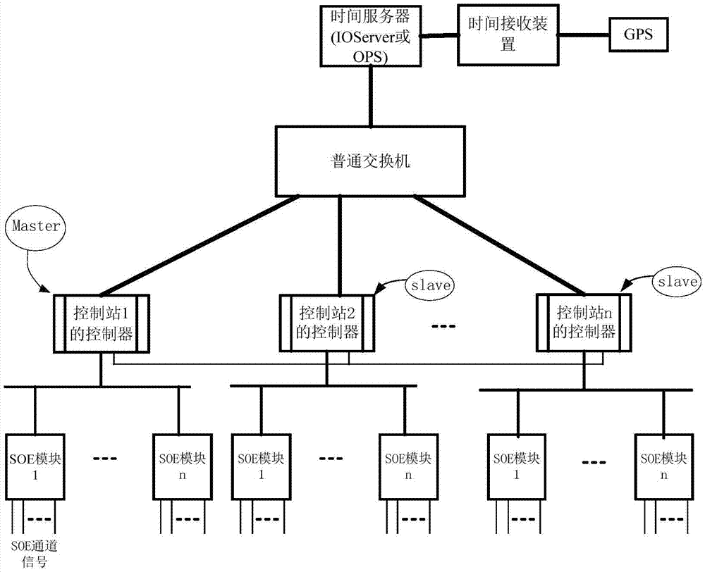
[0078] It is understandable that time synchronization is performed from top to bottom. The clock source is GPS. The time receiving device first obtains the standard time from the GPS, and then the time server and the time receiving device check the time, and then the main controller communicates with the time via NTP. The time server performs time calibration to realize the initial time setting of the main controller.

[0079] It is worth noting that steps s3, s4 a...


PUM


Abstract

The invention discloses an SOE (Sequence of Event) time synchronization control method which is applied to an SOE time synchronization control system. Each controller corresponds to one control station, the controller of one control station is selected in advance as a master controller for time setting, the controllers of the remaining control stations are slave controllers, and the master controller and the slave controllers are connected through hard wiring. The method comprises the following steps: the master controller and the slave controllers of which the initial value of time is preset carry out time synchronization through hard wiring; and the master controller and the slave controllers carry out time synchronization for corresponding SOE modules to realize time synchronization of the SOE modules between the control stations and within the control stations. As the master controller and the slave controllers carry out time synchronization through hard wiring, the precision of time synchronization of the controllers between the control stations is improved (namely, time synchronization of the SOE modules between the control stations and within the control stations is realized), the cost is low, and the balancing between cost and precision is well achieved. The invention further discloses an SOE time synchronization control system.

Description

Technical field [0001] The present invention relates to the technical field of time synchronization, in particular to a SOE time synchronization control method and system. Background technique [0002] In thermal power plant DCS (Distributed Control System, distributed control system or distributed control system) system, substation automation system, hydropower station automation system and other automation control systems, it often involves monitoring the status of a large number of equipment, the status of these equipment may be switch contacts , Breaker contacts, reclosing signals and other open and closed states. For the monitoring of these contact signals, sometimes according to their importance, it is not only necessary to monitor their state changes, but also to monitor and record the moment when their state changes occur. In the same system, the state changes of some devices are related, so it is necessary to use the SOE (SequenceOfEvent, Sequence Of Event Recording Sys...

Claims


Application Information

Patent Timeline
IPC IPC(8): H04J3/06
CPCH04J3/0638
Inventor 周新辉杜军钊李蒙黄振林
Owner HANGZHOU HOLLYSYS AUTOMATION
Why Eureka
Try Eureka