BV line bending and stamping device

A technology of stamping device and stamping die, applied in the field of BV line bending stamping device, can solve the problems of unfavorable production cost control, difficult to use with distribution box, different BV line shapes, etc. , reduce the effect of manual operation

Active Publication Date: 2016-04-06
昇辉控股有限公司
View PDF7 Cites 0 Cited by
  • Summary
  • Abstract
  • Description
  • Claims
  • Application Information

AI Technical Summary

Problems solved by technology

Although this method is simple and easy to operate, for a large-scale processing production line of distribution boxes, its work efficiency is quite low and labor costs are high, which is not conducive to the control of production costs; at the same time, for the processing personnel of the production line, its labor intensity Large, artificially processed BV wires have different shapes, making it difficult to use with distribution boxes

Method used


Image

  • BV line bending and stamping device
  • BV line bending and stamping device
  • BV line bending and stamping device

Examples


Embodiment 1

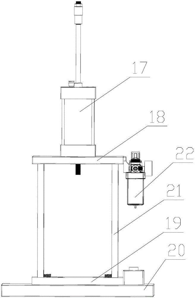
[0046] This embodiment is a BV line bending and punching device, such as figure 1 As shown, including stamping die ( figure 1 Not shown), the punching cylinder 17 and the mold fixing guide frame, the punching mold includes an upper mold and a lower mold, the lower mold is installed on the lower part of the mold fixing guide frame, the upper mold is installed on the upper part of the mold fixing guide frame, and the upper mold is along the mold The fixed guide frame moves up and down above the lower mold, and the end of the punching cylinder is fixedly connected to the top of the upper mold; the top surface of the lower mold is provided with a BV line placement slot, and the BV line placement slot is provided with a bending space for BV line punching 的下孔通槽。 The recessed through slot. The mold fixing guide frame includes an upper mold integral fixing plate 18, a lower mold integral fixing plate 19, a mold fixing chassis 20 and four upper mold guide rods 21. The upper mold guide rod...

Embodiment 2

[0055] This embodiment is a BV line bending and punching device, such as figure 1 As shown, including stamping die ( figure 1 Not shown), the punching cylinder 17 and the mold fixing guide frame, the punching mold includes an upper mold and a lower mold, the lower mold is installed on the lower part of the mold fixing guide frame, the upper mold is installed on the upper part of the mold fixing guide frame, and the upper mold is along the mold The fixed guide frame moves up and down above the lower mold, and the end of the punching cylinder is fixedly connected to the top of the upper mold; the top surface of the lower mold is provided with a BV line placement slot, and the BV line placement slot is provided with a bending space for BV line punching 的下孔通槽。 The recessed through slot. The mold fixing guide frame includes the upper mold integral fixing plate 18, the lower mold integral fixing plate 19, the mold fixing chassis 20, and four upper mold guide rods 21. The upper mold gui...


PUM

PropertyMeasurementUnit
Lengthaaaaaaaaaa
Lengthaaaaaaaaaa

Abstract

The invention discloses a BV line bending and stamping device which comprises a stamping die, a stamping air cylinder and a die fixing and guiding frame. The stamping die comprises an upper die body and a lower die body, the lower die body is installed at the lower portion of the die fixing and guiding frame, the upper die body is installed at the upper portion of the die fixing and guiding frame, the upper die body moves above the lower die body up and down along the die fixing and guiding frame, and the tail end of the stamping air cylinder is fixedly connected with the top of the upper die body; and BV line containing grooves are formed in the top face of the lower die body and a downward-recessed through groove is formed below the BV line containing grooves, wherein a bending space is formed through the downward-recessed through groove when BV lines are stamped. The BV line bending and stamping device is designed to meet the requirement for bending of the BV lines in batches, the device can be suitable for bending the BV lines of different length specifications by arrangement of dies of different structures, use is flexible, the application range is wide, the BV lines of various specifications can be bent in batches, production cost is reduced, and the labor intensity of operators can be lowered.

Description

Technical field [0001] The invention relates to the technical field of BV wire bending, in particular to a BV wire bending and punching device. Background technique [0002] BV wire is abbreviated as plastic copper wire, which is a basic element commonly used in the electrical industry (especially the distribution box production industry). Although the assembly and wiring methods of the distribution box are not the same, the basic principles of the wiring are the same, so in practical applications , It is often required to bend the BV wire into a certain shape before use. The most common shape is the "n" shape, and the commonly used BV wire specifications are mainly 90mm, 100mm and 130mm to 170mm in length. In the current assembly process of the distribution box, the bending of the BV line is generally completed by manual operation. The BV line is placed on a flat plate with fixing screws on the top surface. The BV line is clamped and positioned by two fixing screws installed in ...

Claims


Application Information

Patent Timeline
IPC IPC(8): B21F1/00
CPCB21F1/004
Inventor 李昭强
Owner 昇辉控股有限公司
Why Eureka
Try Eureka