
Air hole pre-setting device for cast sand mold

A technology of air holes and sand molds, which is applied in the field of sand mold casting, and can solve problems such as complex operation, scrapping of castings, poor exhaust effect, etc.

Inactive Publication Date: 2016-04-06
CHONGQING QIANGXIN MACHINERY MFG CO LTD
View PDF5 Cites 3 Cited by
  • Summary
  • Abstract
  • Description
  • Claims
  • Application Information

AI Technical Summary

Problems solved by technology

During the pouring and filling process of the casting mold, the binder and the like encounter high-temperature molten metal, and a large amount of gas is generated in the cavity and needs to be discharged through the sand tire or the exhaust hole, otherwise the molten metal cannot fill the mold when the pressure in the cavity is too high. The cavity may cause choking fire, which will reduce the quality of castings
Therefore, it is necessary to drill air holes on the sand tire to prevent the gas generated during pouring and the original gas in the cavity from being exhausted, causing defects such as air holes in the casting and causing the casting to be scrapped
[0003] At present, air holes are mainly opened on the formed sand mold. The air hole drilling methods used include artificial air hole drilling and a simple air hole drilling device. Such air hole drilling is not only inefficient but also easy to damage the cavity. , this is because the traditional mode is to use a drill bit or an air needle to drill or pierce the air hole from the lower part of the sand box. Shallow will lead to poor exhaust effect; and only one air hole can be drilled at a time. To drill holes in different positions, it is necessary to move the drill bit or sand mold, and the operation is more complicated.

Method used


Image

  • Air hole pre-setting device for cast sand mold
  • Air hole pre-setting device for cast sand mold
  • Air hole pre-setting device for cast sand mold

Examples


Embodiment Construction

[0015] The present invention will be described in further detail below by means of specific embodiments:

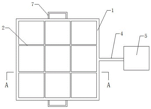
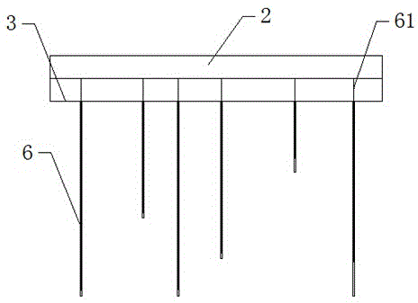
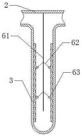
[0016] The reference numerals in the accompanying drawings of the specification include: skeleton 1 , pole 2 , airbag 3 , trachea 4 , air pump 5 , airbag post 6 , pressing rod 61 , ejector rod 62 , support plate 63 , and handle 7 .

[0017] The embodiment is basically as attached figure 1 , figure 2 Shown: the casting sand tire preset air hole device includes a frame body, an air pipe 4 connected to the frame body and an air pump 5 communicated with the air pipe 4 . The frame body includes a skeleton 1 and an airbag 3, the skeleton 1 is in the shape of a rectangular frame, and the interior of the skeleton 1 is provided with a number of struts 2 distributed in a cross shape, and the two ends of the struts 2 are welded on the skeleton 1 . The air bag 3 is fixed on the lower end of the frame 1 and the strut 2 , and the air bag 3 communicates with the trachea 4 . The low...


PUM


Abstract

The invention discloses an air hole pre-setting device for a cast sand mold. The air hole pre-forming device comprises a frame body, an air pipe connected with the frame body and an air pump communicated with the air pipe. The frame body comprises a framework and an air bag. A plurality of supporting rods arranged in a crossed manner are arranged in the framework. The supporting rods are fixed to the framework. The air bag is fixed to the lower ends of the framework and the supporting rods. The air bag is communicated with the air pipe. A plurality of air bag pillars are formed at the lower end of the air bag in a downward protruding manner. Pressing pillars and two supporting plates with arc cross sections are arranged in the air bag pillars. The top ends of the pressing pillars are fixed to the supporting rods. The pressing pillars are located between the corresponding two supporting boards. The outer walls of the supporting plates are fixed to the inner walls of the air bag pillars. Two ejector rods are longitudinally arranged on the inner wall of each supporting plate. The other ends of the ejector rods are connected with the pressing pillars. According to the scheme, the depth, the size and the number of air holes can be preset, multiple air holes can be machined at a time, machining efficiency is improved, compactness and breathability of molding sand cannot be changed, the cast quality cannot be influenced, exhaust effects are good, and operation is simple.

Description

technical field [0001] The invention relates to the field of sand mold casting, in particular to a device for presetting air holes in a casting sand tire. Background technique [0002] The manufacture of traditional sand molds is to use patterns (where patterns can be wooden molds, metal molds, plastic molds, or lost molds, etc.) to find the shape, size and precision of the casting cavity. During the pouring and filling process of the casting mold, the binder and the like encounter high-temperature molten metal, and a large amount of gas is generated in the cavity and needs to be discharged through the sand tire or the exhaust hole, otherwise the molten metal cannot fill the mold when the pressure in the cavity is too high. The cavity may cause choking and reduce the quality of castings. Therefore, it is necessary to drill air holes on the sand tire to prevent the gas generated during pouring and the original gas in the cavity from being exhausted, causing defects such as a...

Claims


Application Information

Patent Timeline
Patent Type & Authority Applications(China)
IPC IPC(8): B22C9/02
CPCB22C9/02
Inventor 王世中
Owner CHONGQING QIANGXIN MACHINERY MFG CO LTD
Learn More