Eureka AIR delivers breakthrough ideas for toughest innovation challenges, trusted by R&D personnel around the world.

Gear machining equipment with automatic positioning function

A processing equipment and automatic positioning technology, which is applied in the field of gear processing, can solve the problems of inconvenient installation and disassembly, and achieve the effect of ensuring coaxiality

Active Publication Date: 2016-04-06
JIAXIANG MACHINERY NINGGUO CO LTD
View PDF6 Cites 4 Cited by
  • Summary
  • Abstract
  • Description
  • Claims
  • Application Information

AI Technical Summary

Problems solved by technology

When the friction between the workpiece and the shaft is too large, it is not easy to install and disassemble the work

Method used


Image

  • Gear machining equipment with automatic positioning function
  • Gear machining equipment with automatic positioning function
  • Gear machining equipment with automatic positioning function

Examples


Embodiment Construction

[0023] In order to make the purpose, technical solutions and advantages of the embodiments of the present invention more clear, specific embodiments will be described in detail below with reference to the accompanying drawings.

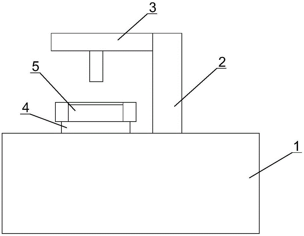
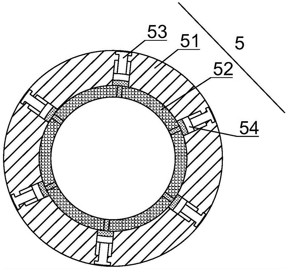
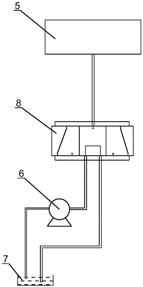
[0024] Such as figure 1 as shown, figure 1 It is a structural schematic diagram of an automatic positioning enterprise processing equipment proposed by the present invention, including a processing table 1, a milling support 2, a milling assembly 3, an adjustment table 4, a positioning plate 5, a controller, a first sensor, a second sensor, Hydraulic pump 6, hydraulic oil tank 7 and electromagnetic hydraulic valve 8.

[0025] The adjustment table 4 is slidably installed on the processing table 1 , the milling support 2 is installed on the processing table 1 , and the milling assembly 3 is slidably installed on the support, and it is located above the adjustment table 4 . The adjustment table 4 is used to adjust the axis of the inner hole of the gear...


PUM


Abstract

The invention discloses gear machining equipment with an automatic positioning function. The gear machining equipment with the automatic positioning function comprises a machining table, a milling support, a milling assembly, an adjusting table, a positioning plate, a controller, a first sensor, second sensors, a hydraulic pump, a hydraulic oil tank and an electromagnetic hydraulic valve, wherein the adjusting table is slidably mounted on the machining table; the milling support is mounted on the machining table; the milling assembly is slidably mounted on the support; the positioning plate is mounted on the adjusting table; the controller is electrically connected with the first sensor, the hydraulic pump and the electromagnetic hydraulic valve; the controller acquires a detection value of the first sensor; the detection value of the first sensor is compared to a first preset value in the controller; and working states of the electromagnetic hydraulic valve and the hydraulic pump are controlled according to a comparison result. The controller is electrically connected with the second sensors and the adjusting table, the controller calculates a deviation position according to detection values of the second sensors and a preset diameter of the positioning plate, and the adjusting table is controlled to move according to a calculated result. By the gear machining equipment with the automatic positioning function, gears to be machined can be positioned, and coaxiality of pitch circles of the gears and shaft holes in the gears is improved.

Description

technical field [0001] The invention relates to the technical field of gear processing, in particular to an automatic positioning gear processing equipment. Background technique [0002] Gear is one of the most commonly used parts in the process of mechanical transmission. In the process of gear processing and positioning, the work is mainly installed on the center shaft, and the workpiece is positioned through the end face and inner hole, and then the center shaft is positioned. Mounted on the chuck for positioning. When the workpiece is positioned by this positioning method, a large frictional force between the workpiece and the center shaft is required to ensure that there will be no relative movement during processing. When the friction force between the workpiece and the center shaft is too large, it is not easy to install and disassemble the work. Contents of the invention [0003] Based on the technical problems existing in the background technology, the present i...

Claims


Application Information

Patent Timeline
IPC IPC(8): B23F23/06
CPCB23F23/06
Inventor 储勇
Owner JIAXIANG MACHINERY NINGGUO CO LTD
Why Eureka
Eureka Blog
Learn More