An intelligent conveying welding system and its conveying method

A welding system and conveying track technology, applied in welding equipment, auxiliary welding equipment, welding/cutting auxiliary equipment, etc., can solve the problems of inconvenient single workpiece conveying, high equipment precision requirements, and expensive intelligent welding equipment, etc. Achieve the effect of improving processing performance and processing efficiency, scientific and reasonable design, and reducing design cost

Active Publication Date: 2017-03-29
重庆市迈雷特数控技术有限公司
View PDF6 Cites 0 Cited by
  • Summary
  • Abstract
  • Description
  • Claims
  • Application Information

AI Technical Summary

Problems solved by technology

[0002] In the existing workpiece welding process, it is usually realized by centralized transmission. The operation is realized by designing the welding head as a movable intelligent structure, which requires high equipment precision, and intelligent welding equipment is expensive and inconvenient. Individual conveying of individual workpieces is required

Method used


Image

  • An intelligent conveying welding system and its conveying method
  • An intelligent conveying welding system and its conveying method

Examples


Embodiment 1

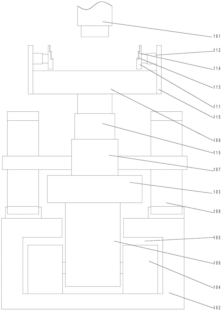
[0023] Such as figure 1 As shown, a welding system for intelligent transportation includes a welding head 101 and a conveying track 102 arranged below the welding head 101. A conveying device 103 is arranged on the conveying track 102. The conveying device 103 The lower end is provided with a roller 104 matched with the conveying track 102, and the middle part of the conveying track 102 is provided with a T-shaped channel 105, and the rollers 104 are arranged symmetrically in the channel 105. 2, a vertical rod 106 is arranged at the lower end of the conveying device 103, and the two rollers 104 are respectively rotatably connected to both sides of the vertical rod 106, and a motor 107 is arranged in the conveying device 103, The output shaft of the motor 107 is provided with two gears 108, and the upper end surface of the conveying track 102 is provided with teeth meshed with the gears 108, and on the upper end surface of the conveying device 103 A support platform 109 is pro...

Embodiment 2

[0029] On the basis of Embodiment 1, this embodiment also discloses an intelligent delivery method, including the following steps:

[0030] S1: Preset the workpiece conveying frequency in the controller, determine the distance between adjacent conveying devices according to the workpiece conveying frequency, detect the distance between adjacent conveying devices by the infrared range finder, and send it to the controller;

[0031] S2: When the conveying device is located under the welding head, the controller sends drive information to the motor to stop the motor and fix the transmission gear to the teeth on the conveying track for fixing;

[0032] S3: The controller sends a driving signal to the welding head, and the welding head starts to run for welding;

[0033] S4: After the welding is completed, the controller sends a driving signal to the motor, and the motor runs to make the transmission gear run along the conveying track;

[0034] S5: When a single conveying device s...


PUM


Abstract

The invention discloses an intelligent conveying welding system which comprises a welding machine head and conveying rails arranged below the welding machine head. A conveying device is arranged on the conveying rails. Wheels matched with the conveying rails are arranged at the lower end of the conveying device. T-shaped through grooves are formed in the middles of the conveying rails. The two wheels are symmetrically arranged in the through grooves. A vertical rod is arranged at the lower end of the conveying device. The two wheels are connected to the two sides of the vertical rod in a rotating mode respectively. A motor is arranged in the conveying device. Two gears are arranged on an output shaft of the motor. The conveying device conveys to-be-welded workpieces along the conveying rails to the position below the welding machine head to be welded, each to-be-welded workpiece can be independently conveyed in the operation process, the anti-collision function can be achieved, the workpieces of different sizes can be conveyed, and the intelligent conveying welding system is simple in structure, flexible to operate and convenient to use.

Description

technical field [0001] The invention relates to an intelligent conveying welding system and a conveying method thereof. Background technique [0002] In the existing workpiece welding process, it is usually realized by centralized transmission. The operation is realized by designing the welding head as a movable intelligent structure, which requires high equipment precision, and intelligent welding equipment is expensive and inconvenient. Individual workpieces need to be transported individually. Contents of the invention [0003] The purpose of the present invention is to provide an intelligent transport welding system and its transport method, which can improve the problems existing in the prior art. By using the transport device along the transport track, the workpiece to be welded is transported to the bottom of the welding head for welding. In the process of operation, a single workpiece to be welded can be transported separately, and can realize the anti-collision f...

Claims


Application Information

Patent Timeline
Patent Type & Authority Patents(China)
IPC IPC(8): B23K37/00
CPCB23K37/00
Inventor 林守金彭泳超钱晓朋罗龙章邹建兵程文发
Owner 重庆市迈雷特数控技术有限公司
Why Eureka
Try Eureka