Compensation gas path for bottle blowing machine

A blow molding machine and compensation gas technology, which is applied in the field of blow molding machine compensation gas path, can solve the problems of affecting blowout and enlarged mold clamping seam, and achieve the effects of compact structure, simplified gas path system, and cost reduction

Active Publication Date: 2017-08-29
JIANGSU NEWAMSTAR PACKAGING MACHINERY
View PDF5 Cites 0 Cited by
  • Summary
  • Abstract
  • Description
  • Claims
  • Application Information

AI Technical Summary

Problems solved by technology

[0002] When the bottle blowing machine blows the bottle, because the cavity of the mold is filled with high-pressure air, the mold must be pushed outward, which will cause the joint to become larger and affect the blown bottle the quality of

Method used


Image

  • Compensation gas path for bottle blowing machine
  • Compensation gas path for bottle blowing machine

Examples


Embodiment Construction

[0020] The technical solution of the present invention will be further described below in conjunction with the accompanying drawings.

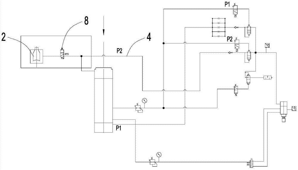
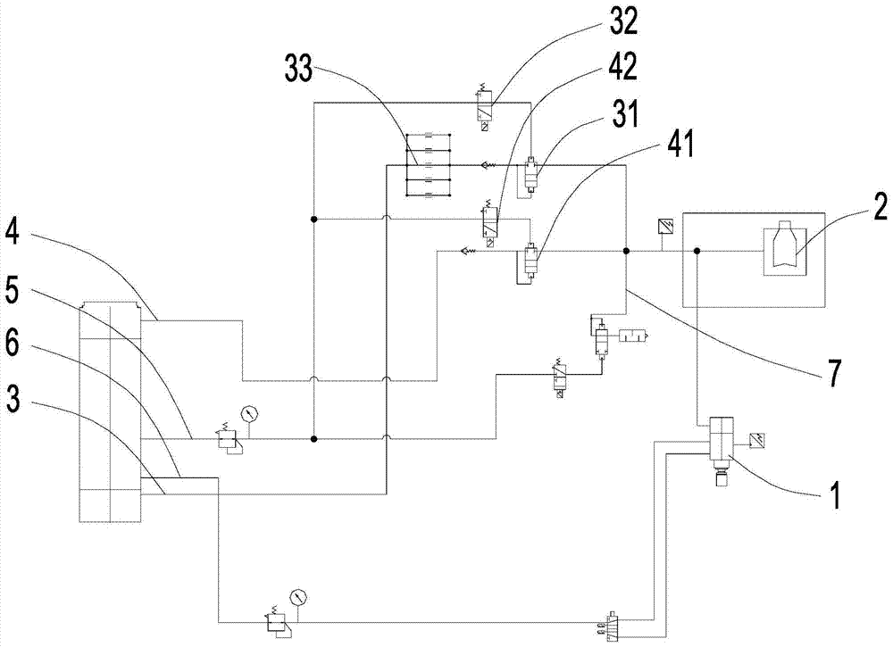
[0021] see figure 2 As shown, the compensation air path of the above-mentioned blow molding machine uses the sealing cylinder 1 that moves up and down to seal the preform and then blows it. The preform is located in the mold 2. The sealing cylinder 1 includes an air inlet valve and an exhaust valve. valve.

[0022] The compensation gas circuit of the bottle blowing machine includes a gas output device, a blowing gas pipeline for blowing the preform, and a compensation gas pipeline for blowing the mold 2. The blowing gas pipeline and the compensation gas pipeline are both It is connected to the exhaust valve, and the blowing gas pipeline and the compensation gas pipeline are simultaneously fed into the blowing gas pipeline through the exhaust valve.

[0023] The gas output device includes a first blowing pipeline 3 for outputting a first hig...


PUM


Abstract

The invention discloses a compensation air path of a bottle blowing machine. Air is blown to a preform through a sealing cylinder. The preform is located in a mould. The sealing cylinder includes an intake valve and an exhaust valve. The compensation air path of a bottle blowing machine includes a gas output device, The blowing gas pipeline for blowing the preform, the compensation gas pipeline for blowing the mold, the blowing gas pipeline and the compensation gas pipeline are all connected to the exhaust valve; the gas output device includes a first channel for outputting The first blowing pipeline for high-pressure gas, the second blowing pipeline for outputting the second high-pressure gas, the first blowing pipeline and the second blowing pipeline are all connected to the intake valve. The device of the present invention connects both the blowing gas pipeline for blowing preforms and the compensation gas pipeline for compensating the mold to the exhaust valve of the sealing cylinder, through the first blowing pipeline connected to the inlet valve of the sealing cylinder The blowing gas pipeline and the compensation gas pipeline are supplied alternately with the second blowing pipeline at the same time, which simplifies the gas system of the blow molding machine and reduces the cost.

Description

technical field [0001] The invention relates to a compensation gas path of a bottle blowing machine. Background technique [0002] When the bottle blowing machine blows the bottle, because the cavity of the mold is filled with high-pressure air, the mold must be pushed outward, which will cause the joint to become larger and affect the quality of the blown bottle. Therefore, the compensation gas is connected to the outside of the mold to compensate the pressure in the mold cavity and eliminate its influence on the mold clamping gap, thereby improving the quality of the blown bottle. [0003] traditional methods such as figure 1 As shown, the compensation gas is connected from the second blowing pipeline 4, connected to the compensation ring pipe through the compensation air pipe, and then connected to the compensation valve 8 through the compensation ring pipe, and connected to the mold base through the compensation valve 8 to output to the mold 2 Compensation gas. Conte...

Claims


Application Information

Patent Timeline
Patent Type & Authority Patents(China)
IPC IPC(8): B29C49/58B29C49/56
CPCB29C49/56B29C49/58B29C2049/563
Inventor 周志鹏潘盛贤吴赟
Owner JIANGSU NEWAMSTAR PACKAGING MACHINERY
Why Eureka
Try Eureka