Power assembly of hybrid power vehicle

A hybrid electric vehicle and powertrain technology, which is applied to the arrangement of multiple different prime movers of power units, pneumatic power units, and general power units, etc. Difficulty, increase the difficulty of sealing the box, etc., to achieve the effect of compact structure, simple structure and easy sealing

Inactive Publication Date: 2016-04-06
SHANGHAI SYNETEC POWER SYST
View PDF9 Cites 2 Cited by
  • Summary
  • Abstract
  • Description
  • Claims
  • Application Information

AI Technical Summary

Problems solved by technology

Through analysis, it is found that the invention has the following defects: since the motor MG1 and the motor MG2 are both hollow-shaft motors, the structure of the motor becomes complicated, which increases the difficulty of processing and manufacturing the motor, thereby increasing the cost and increasing the size of the box. Difficulty of sealing
In addition, since the planetary carrier and the sun gear of the planetary gear mechanism as a comprehensive power distribution mechanism are respectively connected to the engine and the motor MG1, the motor MG1 cannot participate in the drive when the engine does not participate in driving and the entire driving force is provided by the motor. The driving force can only be provided by the motor MG2, which increases the torque capacity requirement of the motor MG2, resulting in an increase in cost

Method used


Image

  • Power assembly of hybrid power vehicle
  • Power assembly of hybrid power vehicle
  • Power assembly of hybrid power vehicle

Examples


Embodiment 1

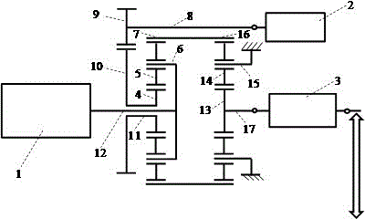
[0086] A hybrid electric vehicle powertrain, such as figure 1 As shown, it includes engine 1, first motor 2, second motor 3, first planetary sun gear 4, first planetary planetary gear 5, first planetary carrier 6, first planetary ring gear 7, the first planetary gear One motor driving gear shaft 8, the first motor driving gear 9, the first motor driven gear 10, the first motor driven gear shaft 11, the first planetary row carrier shaft 12, the second planetary row sun gear 13, the second Planetary row planetary gear 14, second planetary row carrier 15, second planetary row ring gear 16, second planetary row sun gear shaft 17. The engine 1 is connected to the first planetary carrier shaft 12 . The first planetary carrier shaft 12 is connected with the first planetary carrier 6 or made in one piece. The first motor 2 is connected with the first motor driving gear shaft 8 . The first motor driving gear shaft 8 is connected with the first motor driving gear 9 . The first motor...

Embodiment 2

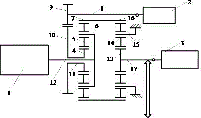
[0088] A hybrid electric vehicle powertrain, such as figure 2 As shown, the basic structure is similar to that of Embodiment 1, except that the system power is output through a gear or chain connected to the second planetary row sun gear shaft 17 or other devices.

Embodiment 3

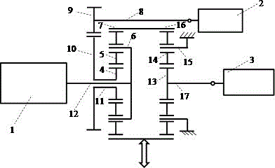
[0090] A hybrid electric vehicle powertrain, such as image 3 As shown, the basic structure is similar to the first embodiment, the difference is that the power of the system is output through the first planetary ring gear 7 or the second planetary ring gear 16 .


PUM


Abstract

The invention relates to a power assembly of a hybrid power vehicle, which comprises a first motor, a second motor, a first planet-row sun gear, a first planet-row planet gear, a first planet-row planet carrier, a first planet-row planet carrier shaft and a first planet-row gear ring, and also comprises a first motor driving gear shaft, a first motor driving gear, a first motor driven gear, a first motor driven gear shaft, a second planet-row sun gear, a second planet-row planet gear, a second planet-row planet carrier, a second planet-row gear ring and a second planet-row sun gear shaft. Compared with the prior art, the first motor and the second motor which are adopted in the invention are solid shaft motors and are simple in structure and easy to process and manufacture; planet rows are adopted to reduce the speed of the second motor and increase the torque of the second motor, so that the volume is small, the structure is compact, the operation is smooth and the work is reliable; and a braking and locking mechanism can be used for braking or locking an engine so as to enable the first motor and the second motor to simultaneously participate in driving.

Description

technical field [0001] The invention relates to a power assembly of a hybrid electric vehicle, in particular to a power assembly of a hybrid electric vehicle with two planetary rows and two solid shaft motors. Background technique [0002] Hybrid electric vehicles are a practical solution to energy and environmental issues at this stage. However, there are certain defects in the existing hybrid electric vehicle powertrain. [0003] Chinese patent ZL200480019795.5 discloses a power output device for a hybrid vehicle. The hybrid vehicle of the invention has an internal combustion engine, a planetary gear unit including a planet carrier connected to the crankshaft of the engine and a ring gear connected to the drive shaft. A motor (MG1) that inputs power to and outputs power from the sun gear of the gear unit, and a motor (MG2) that inputs power to and outputs power from the drive shaft. Through analysis, it is found that the invention has the following defects: since the m...

Claims


Application Information

Patent Timeline
Patent Type & Authority Applications(China)
IPC IPC(8): B60K6/26B60K6/36
Inventor 胡斐张天锷
Owner SHANGHAI SYNETEC POWER SYST
Why Eureka
Try Eureka