Image forming device and paper discharging mechanism thereof

A technology of paper discharge and image, which is applied in the directions of transportation and packaging, sending objects, and thin material handling, etc. It can solve the problem of affecting the stowage performance of the second tray 3 for paper discharge, the inability of paper P to be discharged neatly, and the inability of paper P to be discharged smoothly, etc. problem, to avoid waist collapse, reduce the amount of bending, and enhance the strength

Active Publication Date: 2016-04-06
KONICA MINOLTA TECH DEV WUXI
View PDF6 Cites 8 Cited by
  • Summary
  • Abstract
  • Description
  • Claims
  • Application Information

AI Technical Summary

Problems solved by technology

[0006] However, the paper discharge mechanism of the above-mentioned conventional image forming apparatus has the following problem: in the process of pushing the paper P on the first tray 1 to the second tray 3 by the pushing part 2, if the paper P is not bound or clamped, Then the paper may be skewed (that is, the rear end of the paper is no longer completely attached to the ejection part 2), and the paper P cannot be discharged neatly.
This will not only cause the rear end of the paper P to escape from the pressure part 4 before the paper P is completely discharged (that is, the pushing part 2 stops pushing the paper P), so that the paper P cannot be discharged smoothly, but also cause: Figure 4 As shown, even if the paper P is discharged smoothly, the rear end of the paper P will be placed on the second tray 3 in a bent state, which will affect the next discharge of paper and the stowage performance of the second tray 3

Method used


Image

  • Image forming device and paper discharging mechanism thereof
  • Image forming device and paper discharging mechanism thereof
  • Image forming device and paper discharging mechanism thereof

Examples


no. 1 example

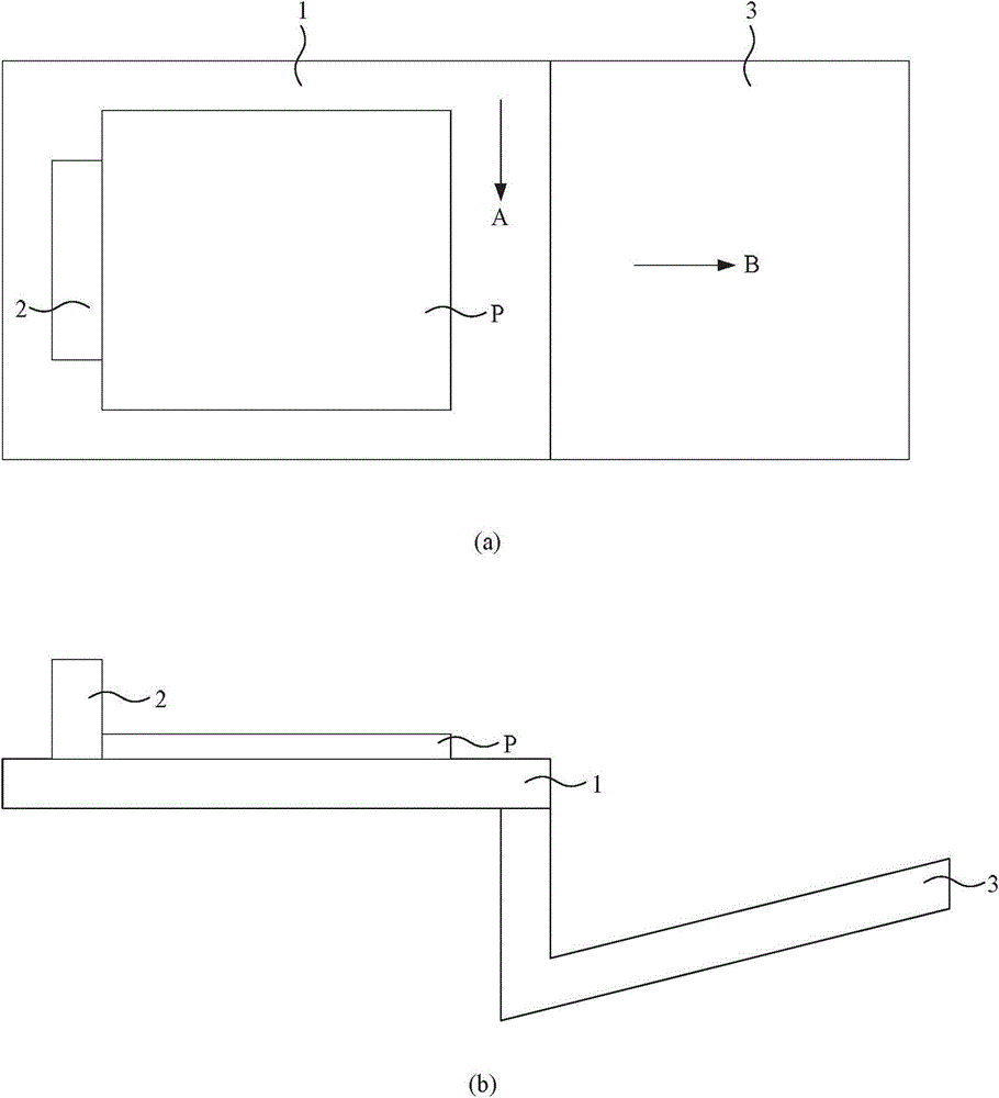
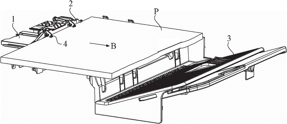
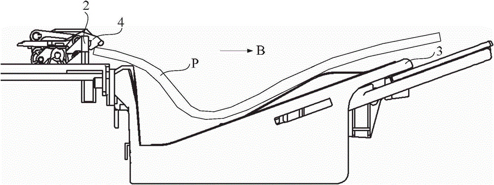
[0044] combine Figure 5 to Figure 6 As shown, the paper discharge mechanism 1 of this embodiment includes: a first tray 10, used to carry the paper P discharged from the paper outlet (not shown) of the image forming apparatus along the discharge direction A; The paper P (the number is one or more) on the first tray 10 is pushed out along the paper discharge direction B; the second tray 30 is located downstream of the first tray 10 along the paper discharge direction B to carry the paper pushed out by the pusher 20, The upstream end of the second tray 30 is lower than the downstream end of the first tray 10; the pressure part 40 is used to press the paper P on the first tray 10; One side of the second tray 30 can support the protrusion 50 when the paper P is discharged along the paper discharge direction B, and forms an arched shape extending along the paper discharge direction B.

[0045] The paper on which the image is formed is discharged from the paper outlet of the image...

no. 2 example

[0062] The difference between the second embodiment and the first embodiment is: as Figure 10 As shown, in the second embodiment, the number of protrusions 50 on the first tray 10 is multiple (two are taken as an example in the figure), and the plurality of protrusions 50 are along the direction perpendicular to the paper discharge direction B (in this paper In the embodiment, the discharge direction A) is also arranged at intervals, and the number of convex portions 60 on the second tray 30 is multiple, and the plurality of convex portions 60 are along the direction perpendicular to the paper discharge direction B (also the discharge direction in this embodiment). A) Arranged at intervals, each protruding portion 50 is located on a straight line along the paper discharge direction B with a corresponding one of the protruding portions 60 .

[0063] Additionally, if Figure 11 As shown, the present invention also provides an image forming device, which includes the paper disc...

no. 3 example

[0065] The difference between the third embodiment and the first and second embodiments is: as Figure 12 As shown, in the third embodiment, the ejection direction A is consistent with the paper ejection direction B; a plurality of protrusions 50 are arranged at intervals along a direction perpendicular to the paper ejection direction B and the ejection direction A, and a plurality of protrusions 60 are also arranged along the direction perpendicular to the ejection direction B; They are arranged at intervals in the direction perpendicular to the paper direction B and the discharge direction A.

[0066] In addition, the present invention also provides an image forming device, which includes the paper discharge mechanism of the third embodiment, and the second tray and the operation panel of the image forming device are not located on the same side.


PUM


Abstract

The invention discloses an image forming device and a paper discharging mechanism thereof. The paper discharging mechanism comprises a first tray, a pushing part, a second tray, a pressure part and a protrusion part, wherein the first tray is used for bearing paper discharged from a paper outlet in the discharging direction; the pushing part is used for pushing out the paper on the first tray in the paper discharging direction; the second tray is located on the downstream part of the first tray in the paper discharging direction to bear the paper pushed out by the pushing part, and the upstream end of the second tray is lower than the downstream end of the first tray; the pressure part is used for pressing the paper on the first tray; the protrusion part is located on the side, near the second tray, of the first tray in the paper discharging direction, and the paper can be supported on the protrusion part when discharged in the paper discharging direction and forms an arch shape extending in the paper discharging direction. The novel paper discharging mechanism is invented and does not damage paper, and the problem that the waist part collapses when the paper is discharged in the paper discharging direction is avoided.

Description

technical field [0001] The invention relates to an image forming device and a paper discharge mechanism thereof. Background technique [0002] With the rapid development of science and technology, human beings have already entered the information age. Computer peripheral products and other related image forming devices, such as copiers, printers, scanners, fax machines, photocopiers or multi-functional ones with functions such as copying, scanning, printing and faxing The MFP can not only help improve the efficiency of people's processing information, but also speed up the communication between people. [0003] As user needs become more and more diverse, the functions of existing image forming devices are not limited to forming images on paper, but can also implement the following function: post-processing the paper on which images are formed. For example, the post-processing may be punching, stapling, clamping and so on. [0004] An existing image forming apparatus capabl...

Claims


Application Information

Patent Timeline
Patent Type & Authority Applications(China)
IPC IPC(8): B65H33/14
Inventor 许江涛李健方静
Owner KONICA MINOLTA TECH DEV WUXI
Why Eureka
Try Eureka