Washing machine deceleration clutch and washing machine

A deceleration clutch and washing machine technology, which is applied in the field of washing machines, can solve the problems of large space occupied by the deceleration clutch, smaller washing tub space, and increased volume of the washing machine, so as to reduce the space occupied by the axial direction, increase the washing capacity, and save The effect of axial space

Active Publication Date: 2016-04-06
QINGDAO HAIER WASHING MASCH CO LTD
View PDF3 Cites 7 Cited by
  • Summary
  • Abstract
  • Description
  • Claims
  • Application Information

AI Technical Summary

Problems solved by technology

However, the general deceleration clutch clutch device and the deceleration device are located in the same axial direction, and the general motor, clutch device, and deceleration device are arranged in sequence along the axial direction. In this way, the space occupied by the deceleration clutch will be large, and if the space occupied by the deceleration clutch is large, In the shell of the same volume, the space of the washing drum will be smaller, and the washing capacity will be smaller. If the washing capacity cannot be reduced, the volume of the washing machine needs to be increased. How can a washing machine of the same volume achieve the maximum washing capacity? Capacity is an issue that needs to be studied,

Method used


Image

  • Washing machine deceleration clutch and washing machine
  • Washing machine deceleration clutch and washing machine
  • Washing machine deceleration clutch and washing machine

Examples


Embodiment 1

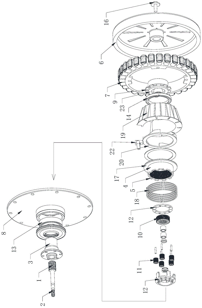
[0039] Such as Figure 1-2As shown, a deceleration clutch for a washing machine includes: an input shaft 1, a deceleration device, a clutch device, an output shaft 2 and an output shaft sleeve 3, and the clutch device includes a clutch pressure plate 20 and a clutch sleeve 21, and the clutch sleeve 21 Set on the peripheral periphery of the reduction gear, the projection on the straight line where the input shaft is located is at least partially overlapped, and the rotation of the clutch pressure plate 20 drives the clutch sleeve 21 to move axially; the reduction gear includes a reduction gear train and a reduction gear train The meshing ring gear; preferably, the reduction gear includes a planetary gear 11, and the clutch sleeve 21 is an inner ring gear that meshes with the planetary gear and can move axially; the clutch sleeve 21 moves axially Control the output shaft 2 and the output shaft sleeve 3 to realize the dehydration / washing working condition.

[0040] If the above-...

Embodiment 2

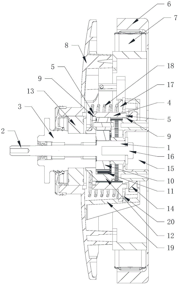
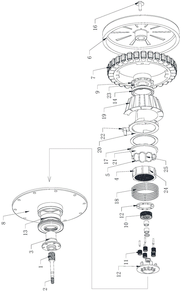
[0072] Such as image 3 , Figure 4 As shown, a washing machine deceleration clutch according to the present invention includes: an input shaft 1, a deceleration device, a clutch device, an output shaft 2 and an output sleeve 3, and the clutch device includes a clutch pressure plate 20 and a clutch sleeve 21, The clutch bushing 21 is set on the peripheral periphery of the reduction gear, and the rotation of the clutch pressure plate 20 drives the clutch bushing 21 to move axially; the reduction gear includes a planetary gear 11, and the clutch bushing 21 is for intermeshing with the planetary gear and can An axially movable ring gear, or the deceleration device includes a planetary gear 11 and an inner ring gear 4 that mesh with each other, and the clutch sleeve 21 and the ring gear 4 are engaged with each other and can move axially; the clutch sleeve 21 Axial movement controls the output shaft 2 and the output shaft sleeve 3 to realize the dehydration / washing working conditi...

Embodiment 3

[0105] Such as Figure 1-7 As shown, a deceleration clutch for a washing machine includes: an input shaft 1, a deceleration device, a clutch device, an output shaft 2 and an output shaft sleeve 3, and the clutch device includes a clutch pressure plate 20 and a clutch sleeve 21, and the clutch sleeve 21 Installed on the periphery of the reduction gear, the clutch pressure plate 20 drives the clutch sleeve 21 to move axially to control the output shaft 2 and the output sleeve 3 to achieve dehydration / washing conditions; the clutch pressure plate 20 is connected to a drive motor, The driving motor drives the clutch pressure plate 20 to rotate.

[0106] The deceleration clutch of the washing machine of the present invention adopts the rotational movement of the clutch pressure plate 20 to drive the clutch shaft sleeve 21 to move axially to realize clutching. Since the clutch pressure plate 20 is used to rotate and drive the clutch mode, and the clutch sleeve 21 is set on the perip...


PUM


Abstract

The invention provides a washing machine deceleration clutch and a washing machine. The washing machine deceleration clutch comprises an input shaft, a deceleration device, a clutch device, an output shaft and an output shaft sleeve, wherein the clutch device is formed by a clutch platen and a clutch shaft sleeve; the clutch shaft sleeve covers the circumferential periphery of the deceleration device; the clutch platen rotationally move surrounding the axis to drive the clutch shaft sleeve to axially move; a first position of the clutch shaft sleeve movement is connected with a fixing device; the fixing device and an external cylinder of the washing machine are relatively fixed, so a washing work condition can be achieved; a second position of the clutch shaft sleeve movement is connected with a rotor of a direct-drive motor, so a dehydrating work condition can be achieved. The clutch device is arranged on the circumferential periphery of the deceleration device, so overall height of the deceleration clutch can be reduced, washing machine size can be reduced with the same of the washing capacity or washing capacity can be increased with the same of the washing machine size.

Description

technical field [0001] The invention relates to the technical field of washing machines, in particular to a washing machine deceleration clutch and a washing machine. Background technique [0002] Washing machines are household appliances commonly used in people's daily life. They are installed in different ways and can be divided into drum washing machines and pulsator washing machines. A drum washing machine generally includes an outer tub, a drum and a motor, and the motor drives the drum to rotate in the outer tub to wash or dehydrate the clothes. Present drum washing machines simply utilize the rotation of the drum for washing, and only use the lifting ribs in the drum to lift and drop the laundry to beat the clothes for washing, so it is difficult to obtain excellent washing effect. The current drum washing machine also has a pulsator in the drum, and the pulsator and the drum are respectively driven by independent motors to optimize the washing effect. Due to the us...

Claims


Application Information

Patent Timeline
Patent Type & Authority Applications(China)
IPC IPC(8): D06F37/30D06F37/40F16D48/00
Inventor 迟宗锐栾厚利李全德肖磊陈志李作强
Owner QINGDAO HAIER WASHING MASCH CO LTD
Why Eureka
Try Eureka