Clutch apparatus

A technology of clutch device and clutch sleeve, which is applied in the field of washing machines, can solve the problems of troublesome manufacturing and installation, large support connectors, large direct drive motors, etc., and achieve the effect of simplifying manufacturing and installation, meeting installation requirements, and convenient and quick installation

Active Publication Date: 2016-04-06
QINGDAO HAIER WASHING MASCH CO LTD
View PDF9 Cites 7 Cited by
  • Summary
  • Abstract
  • Description
  • Claims
  • Application Information

AI Technical Summary

Problems solved by technology

[0005] The above-mentioned invention patents set the supporting connector of the stator in a concave shape and directly fix it on the reducer casing by screws. The installation method is not suitable for large-capacity washing machines, mainly because: for large The capacity washing machine uses a direct drive motor with a large power, so the volume of the stator is also large. If the support connector is directly connected to the reducer shell, the volume of the support connector is also large, and the connecting part of the support connector Only in the middle, the stability of the connection cannot be guaranteed, and the volume of the supporting connector needs to be very large, making it more troublesome to manufacture and install

Method used


Image

  • Clutch apparatus
  • Clutch apparatus
  • Clutch apparatus

Examples


Embodiment 1

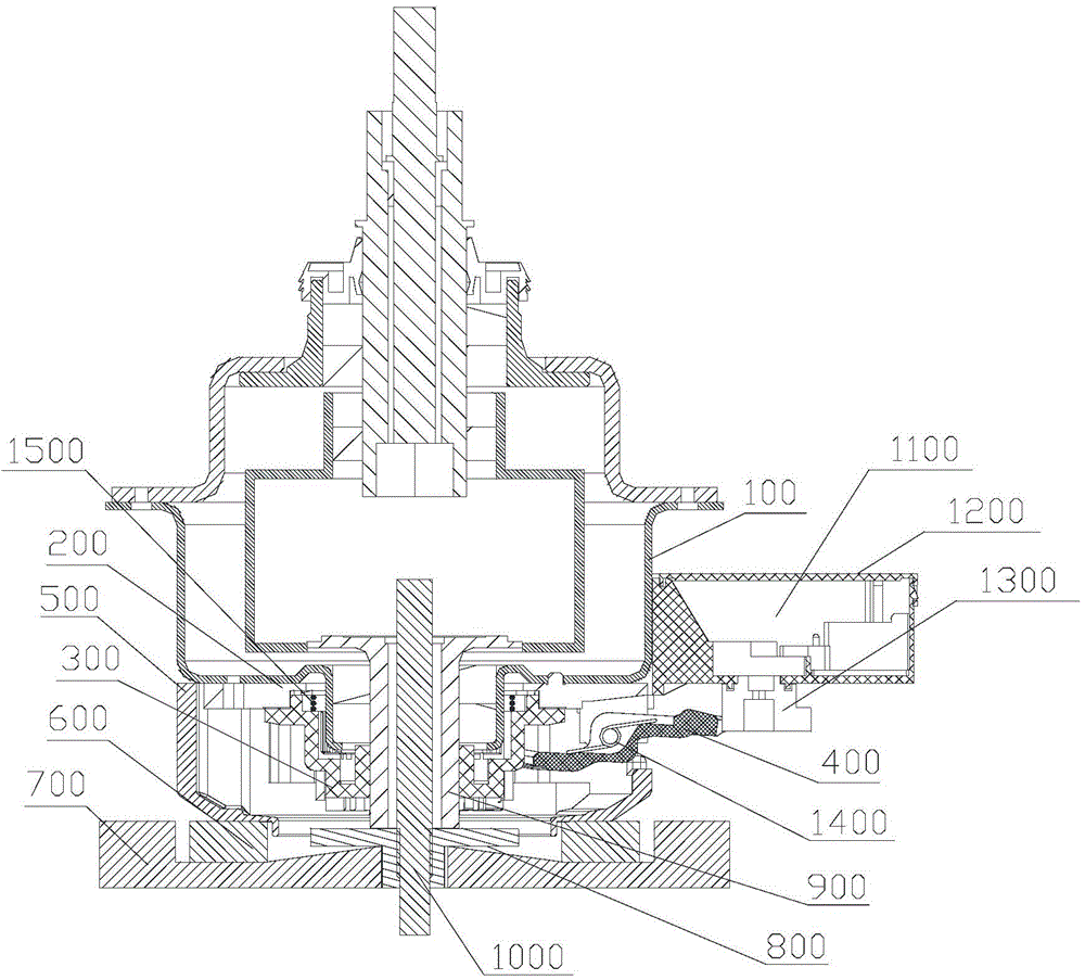
[0044] Such as Figure 3 to Figure 6 As shown, a deceleration clutch clutch driving device described in this embodiment includes a driving motor 1100, a driving wheel 1300 and a shift fork lever 400, the driving wheel 1300 is installed on the motor shaft of the driving motor 1100, and the circumference of the driving wheel 1300 is provided with supports The support surface has a height difference in the axial direction. The shift fork lever 400 is a lever structure, and the middle part is provided with a fixed fulcrum 420. The head of the shift fork lever 400 is a shift fork 410, and the shift fork 410 is located below the clutch sleeve 300. The spring 1500 controls the up and down movement of the clutch sleeve 300 together. The tail of the shift fork lever 400 is the driving end 430, and the driving end 430 is provided with a sliding contact surface, which is slidingly matched with the supporting surface; the driving motor 1100 drives the driving wheel 1300 to rotate, and the ...

Embodiment 2

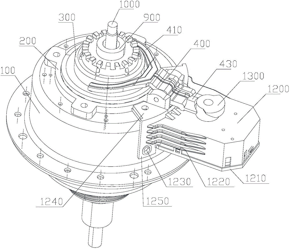
[0058] Such as Figure 2 to Figure 3 As shown, a clutch drive installation structure is introduced in this embodiment. The clutch drive includes a drive motor 1100, a drive wheel 1300 and a fork lever 400. The drive wheel 1300 is installed on the output shaft of the drive motor 1100. The drive motor 1100 is fixedly installed on the housing 100 of the deceleration clutch. Preferably, the driving motor 1100 is installed in the installation cover 1200 , and the installation cover 1200 is fixed on the casing 100 .

[0059] The installation cover 1200 is composed of a hollow cover for the drive motor 1100. One side of the installation cover 1200 is an installation side wall, and the installation side wall is provided with an outwardly protruding installation flange 1250. The mounting flange 1250 is detachably connected to the shell 100 via bolts.

[0060] Such as image 3 As shown, the installation side wall of the installation cover 1200 and the installation flange 1250 are bot...


PUM


Abstract

The invention provides a clutch apparatus comprising a decelerator, a clutch mechanism and a motor. The decelerator is provided with a housing; the motor has a rotor and a stator; the stator is arranged outside the stator; the clutch mechanism is formed by an upper fixing disc, a clutch sleeve capable of sliding up and down and a lower dehydrating disc; the clutch sleeve slides up and down to be respectively engaged with the upper fixing disc and the lower dehydrating disc, so work conditions of washing and dehydration can be switched; the upper fixing disc and the stator are respectively fixedly connected with the lower end surface of the housing; the stator is fixedly connected with the housing via a connection member; and the connection member is an independent part component. With the independent connection member, the rotor of the motor can be connected with the housing of the decelerator, so an installation of the motor of a large-capacity washing machine can be achieved and the motor can be conveniently and quickly installed.

Description

technical field [0001] The invention relates to the field of washing machines, in particular to a clutch device. Background technique [0002] As a daily household appliance, washing machine liberates people from the labor of doing laundry, so it is very popular among users. However, with the rapid development of society, people have higher and higher requirements for washing machines, including people's higher and higher requirements for the capacity of washing machines. Therefore, large-capacity washing machines are thus produced. [0003] Since the washing capacity of the large-capacity washing machine is larger, more power is needed to drive the washing, so a more powerful motor is required to provide power. The larger the power of the motor, the larger the volume. Therefore, the motor installation method of the clutch device of the existing washing machine is used to install the motor of the large-capacity washing machine, which cannot ensure the stability of the insta...

Claims


Application Information

Patent Timeline
Patent Type & Authority Applications(China)
IPC IPC(8): D06F37/40
Inventor 张刚金李峰田云龚孟虎
Owner QINGDAO HAIER WASHING MASCH CO LTD
Why Eureka
Try Eureka