Slot-type embedded part and application node structure of same

A technology of embedded parts and grooves, which is applied to building components, building structures, walls, etc., can solve the problems of large volume of embedded parts, difficult to embed, and difficult to correct the deviation of the embedded position, etc. The effect of convenient construction and high precision

Inactive Publication Date: 2016-04-06
DUOWEI UNION GRP
View PDF16 Cites 3 Cited by
  • Summary
  • Abstract
  • Description
  • Claims
  • Application Information

AI Technical Summary

Problems solved by technology

[0006] The technical problem to be solved by the present invention is to provide a trough-type embedded part and the application node structure of the trough-type embedded part, which solves the problem that the embedded part at the present stage has a large volume, is difficult to embed, and is difficult to correct the deviation of the pre-embedded position technical issues

Method used


Image

  • Slot-type embedded part and application node structure of same
  • Slot-type embedded part and application node structure of same
  • Slot-type embedded part and application node structure of same

Examples


Embodiment 1

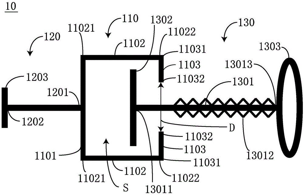
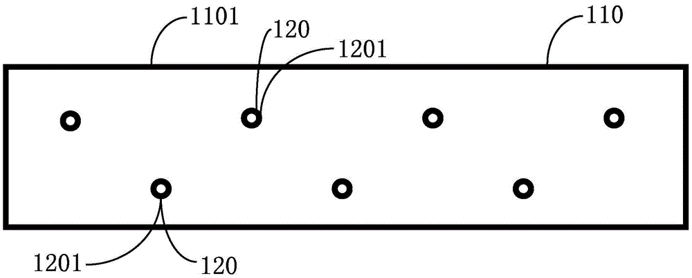
[0044] In order to solve the technical problems that the embedded parts at the present stage are bulky, difficult to embed, and difficult to correct the deviated embedded position. Such as Figure 1-3Shown are the structural schematic diagrams of the trough embedded parts 10 according to the first embodiment of the present invention. The trough embedded parts 10 include a trough connection part 110 , a plurality of anchor bars 120 and a plurality of T-bolts 130 .

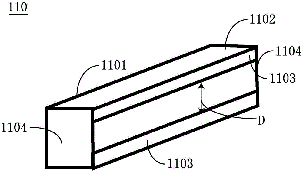
[0045] The trough connection part 110 includes a waist body 1101, two supporting legs 1102 and two barrier parts 1103, the first ends 11021 of the two supporting legs 1102 are respectively connected to the top and bottom of the waist body 1101, and the two barrier parts The first ends 11031 of the part 1103 are respectively connected to the second ends 11022 of the two supporting legs 1102, and the second ends 11032 of the two blocking parts 1103 are respectively bent toward the middle of the waist 1101 and separate...

Embodiment 2

[0055] In order to solve the technical problems that the embedded parts at the present stage are bulky, difficult to embed, and difficult to correct the deviated embedded position. Such as Figure 4-5 As shown, they are schematic diagrams of the application node structure of a trough embedded part of the present invention. The application node of the trough embedded part includes a trough embedded part 10, a concrete member 20 and an external structural connecting plate connecting plate.

[0056] The trough embedded part 10 includes a trough connection part 110 , a plurality of anchor tendons 120 and a plurality of T-bolts 130 . The trough embedded part 110 includes a waist 1101, two supporting legs 1102 and two partitions 1103, the first ends 11021 of the two supporting legs 1102 are respectively connected to the top and bottom of the waist 1101, and the two partitions The first ends 11031 of the blocking parts 1103 are respectively connected to the second ends 11022 of the ...


PUM


Abstract

The invention discloses a slot-type embedded part and an application node structure of the slot-type embedded part. The slot-type embedded part comprises a slot-type connecting portion, a plurality of anchor bars and a plurality of T-shaped bolts. The slot-type connecting portion comprises a waistline, two supporting legs, and two blocking portions. The first ends of the two supporting legs are connected with the top and the bottom of the waistline. The first ends of the two blocking portions are connected with the second ends of the two supporting legs. The second ends of the two blocking portions bend toward the middle part of the waistline, and a distance is between the second ends. The two supporting legs and the two blocking portions are on the same side of the waistline. The first end of the anchor bar is connected with a side of the waistline. The T-shaped bolt comprises a screw, an abutting and clamping portion, and a nut. The abutting and clamping portion is vertically connected with the first end of the screw. The length of the abutting and clamping portion is larger than the distance and smaller than the distance between the two supporting legs. The axial dimension of the abutting and clamping portion is smaller than the distance. The surface of the screw is provided with threads. The nut is sleeved on the screw from the second end of the screw through the threads.

Description

technical field [0001] The invention relates to the field of building materials, in particular to a groove-type embedded part and an application node structure of the groove-type embedded part. Background technique [0002] In the field of modern architecture, frame structure buildings occupy a relatively large proportion because of their high overall strength and fast construction speed. Its main body is generally a concrete column and a floor slab, and then add curtain wall panels around it. The curtain wall panels include metal curtain walls and glass curtain walls. is the key to construction. Taking the metal curtain wall panel as an example, it must first be connected to the wall skeleton, and then connected to the embedded parts set in the concrete components (mainly referring to the column and the floor slab), so as to realize the connection between the metal curtain wall panel and the concrete component. [0003] At present, most of the construction industry choose...

Claims


Application Information

Patent Timeline
Patent Type & Authority Applications(China)
IPC IPC(8): E04B2/88
CPCE04B2/88
Inventor 刘杰
Owner DUOWEI UNION GRP
Why Eureka
Try Eureka