External thermal insulation cement decoration panel with punching metal strips pre-embedded in end surfaces on two sides of same

A technology for punching metal plates and decorative panels, applied in the direction of floor, covering/lining, construction, etc., can solve the problems of poor sealing of the four sides of the mold, time-consuming construction and assembly, unsatisfactory flatness of the steel mesh, etc., to achieve accurate Pre-embedded positioning, accurate shape and size effect

Inactive Publication Date: 2016-04-06
上海丽祥节能科技股份有限公司
View PDF6 Cites 2 Cited by
  • Summary
  • Abstract
  • Description
  • Claims
  • Application Information

AI Technical Summary

Problems solved by technology

[0002] In the patent application document with the application number 201410624106.9 and titled "Method for Forming Cement Decorative Panel Using Laminated Mold Box and Steel Wire Mesh Separation and Laying", a scheme of cement decorative panel with steel mesh on four sides is disclosed. During the implementation, many problems were found, such as the flatness of the steel mesh cannot meet the requirements of the production molding process, it is difficult to accurately pre-embed the steel mesh in the mold, the four sides of the mold are not tightly sealed, resulting in burrs, and mortar filling and pointing during construction and assembly heavy workload
If these problems are not solved, it will be difficult to realize mechanized production, and the construction and assembly will be labor-intensive and time-consuming.

Method used


Image

  • External thermal insulation cement decoration panel with punching metal strips pre-embedded in end surfaces on two sides of same
  • External thermal insulation cement decoration panel with punching metal strips pre-embedded in end surfaces on two sides of same
  • External thermal insulation cement decoration panel with punching metal strips pre-embedded in end surfaces on two sides of same

Examples


Embodiment Construction

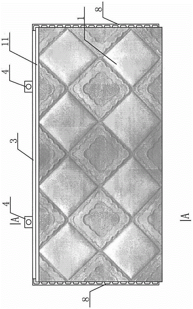
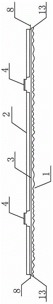
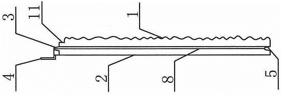
[0026] Such as Figure 1-Figure 13 The cement decorative panel used for the external thermal insulation of the exterior wall shown is equipped with a metal or non-metal mesh 10 inside, a three-dimensional decorative pattern 1 is prefabricated on the outer side, and a concave edge 11 of appropriate width and depth is provided on the upper edge; the inner side 2 is a plane , the upper end surface is provided with a long convex key 3, and metal pendants 4 are arranged at a certain distance, flanges 13 of appropriate height are arranged on the outer edges of the end surfaces of both sides, and punched metal laths 8 are pre-embedded, and punched metal laths 8 Appropriate width of the protruding side end surface; when the cement decorative panel is constructed and assembled, the horizontal seam method is: the lower end surface of the upper row of boards is superimposed on the end face of the next row of boards, and the full length of the upper end of the next row of boards is convex....


PUM


Abstract

The invention discloses an exterior wall external thermal insulation cement decoration panel with punching metal strips pre-embedded in end surfaces on the two sides of the same. The decoration panel is characterized in that the decoration panel is internally provided with a metal or nonmetal net; three-dimensional decorative patterns are prefabricated on the outer side surface of the decoration panel; an concave edge having appropriate width and depth is arranged on the upper edge of the decoration panel; a full-length bulged key is arranged on the upper end surface of the decoration panel; metal hangers are arranged on the upper end surface of the decoration panel at a certain interval; the end surfaces on the two sides are flat surfaces or flanges with appropriate height are arranged on the edges of the outer sides of the end surfaces; and the punching metal strips are pre-embedded in the end surfaces on the two sides of the decoration panel. When cement decoration panels are assembled, horizontal seams are sunk-key type seams; horizontal dividing seams are formed by the concave edges; vertical seams are punching metal strip lap seams filled with mortar; and vertical dividing seams having the depth identical to that of the horizontal dividing seams are formed. The punching metal strips are high in flatness and high in shape and size accuracy, and well meet requirements of cement decoration panel production. The punching metal strip lap seams are high in tensile strength, and motor can be effectively prevented from cracking and leaking.

Description

technical field [0001] The invention belongs to a cement decorative panel for external wall heat preservation with pre-embedded perforated metal laths on the end faces on both sides. Background technique [0002] In the patent application document with the application number 201410624106.9 and titled "Method for Forming Cement Decorative Panel Using Laminated Mold Box and Steel Wire Mesh Separation and Laying", a scheme of cement decorative panel with steel mesh on four sides is disclosed. During the implementation, many problems were found, such as the flatness of the steel mesh cannot meet the requirements of the production molding process, it is difficult to accurately pre-embed the steel mesh in the mold, the four sides of the mold are not tightly sealed, resulting in burrs, and mortar filling and pointing during construction and assembly The workload is large, etc. If these problems are not solved, it will be difficult to realize mechanized production, and the construc...

Claims


Application Information

Patent Timeline
Patent Type & Authority Applications(China)
IPC IPC(8): E04F13/075E04F13/076
CPCE04F13/0889E04F13/0891E04F13/0894E04F2201/021E04F2201/043E04F2290/04
Inventor 虞新华高丽娜
Owner 上海丽祥节能科技股份有限公司
Why Eureka
Try Eureka