Treasury door locking mechanism

A locking mechanism, a technology for vault doors, applied in building structures, building fastening devices, buildings, etc., can solve the problems of inconvenient door opening, high strength requirements, small transmission force, etc., and achieve increased reliability and safety. High and rigid effect

Inactive Publication Date: 2016-04-06
XIANGYANG BOYA PRECISION IND EQUIP
View PDF0 Cites 2 Cited by
  • Summary
  • Abstract
  • Description
  • Claims
  • Application Information

AI Technical Summary

Problems solved by technology

At present, most of the locking mechanisms of vault doors use the traditional locking method. The bolt of the lock is directly embedded in the main locking part, which can prevent violent opening to a certain extent. However, when the traditional locking method is opened violently, The force transmitted by the mechanism directly acts on the lock tongue, which requires high strength for the lock tongue and the parts that interact with the lock tongue; in addition, in order to prevent violent opening of the door, the required transmission force is usually relatively small, and the force required for opening the door is relatively small. Large, it is inconvenient to open the door when the parts are aged and corroded

Method used


Image

  • Treasury door locking mechanism

Examples


Embodiment Construction

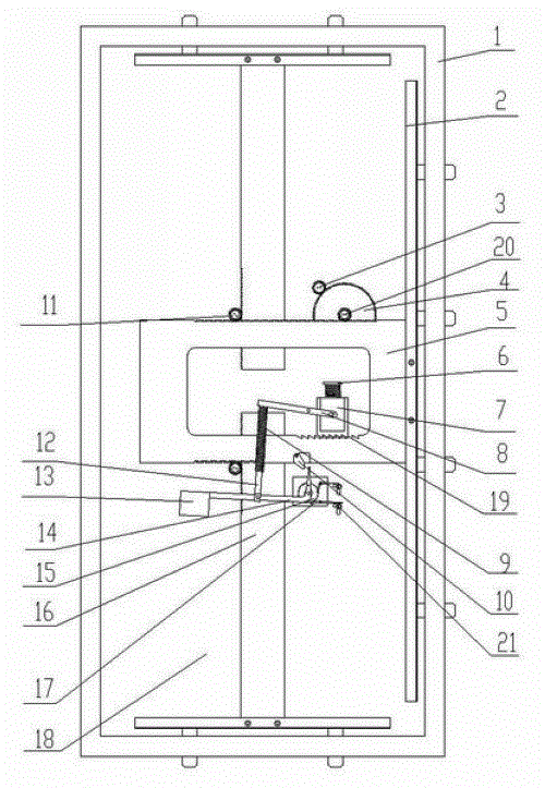
[0015] Such as figure 1 Shown, the present invention comprises storehouse door 18 and door frame 1, and the handwheel of storehouse door 18 outsides is connected with the gear 3 of storehouse door 18 inboards, and gear 3 meshes with transmission gear one 4, and the pinion 20 on the transmission gear one 4 and main One end of the rack of the locking part 5 engages, and the other end of the rack of the main locking part 5 engages with the upper and lower bolts 16 respectively through the transmission gear 211, and one side of the main locking part 5 is equipped with a lock. Tongue 2; the main locking part 5 cooperates with the locking linkage part, and the ends of the upper and lower dead bolts 16 and the dead bolt 2 are inserted in the door frame 1, and the vault door is locked.

[0016] The main locking part 5 meshes with the helical tooth block 7 of the locking linkage part through the helical teeth 19 thereon, the helical tooth block 7 is connected with one end of the lever ...


PUM


Abstract

The invention discloses a treasury door locking mechanism, and relates to the field of locks. A treasury door outer side hand wheel is connected with a treasury door inner side gear, the gear is engaged with a transmission gear 1, a pinion on the transmission gear 1 is engaged with one end of the tooth bar of a main locking part, the other end of the tooth bar of the main locking part is respectively engaged with an upper dead bolt and a lower dead bolt through a transmission gear 2, and one side of the main locking part is provided with a dead bolt; the main locking part fits with a locking linkage part, and the tail ends of the upper dead bolt and the lower dead bolt and the dead bolt are inserted to a door frame to lock a treasury door; the main locking part is engaged with the oblique tooth block of the locking linkage part through an oblique tooth on the main locking part, the oblique tooth block is connected with one end of a lever, and the other end of the lever is connected with a pulling rod through a spring; the pulling rod is connected with a deflector rod 1 through a pin roll, one end of the deflector rod 1 is provided with a balancing weight, and the other end of the deflector rod 1 is connected with a ratchet; and the main locking part moves to the right, a movable block on the main locking part pushes the tip of the deflector rod 1, and the whole locking mechanism is fixed by a deflector rod 2 on the above treasury door. The treasury door locking mechanism has the advantages of reliable movement, firm locking and high safety.

Description

technical field [0001] The invention relates to the technical field of locks, in particular to a vault door locking mechanism. Background technique [0002] In the lock industry, the locking function of the locking mechanism is realized by the moving parts of the locking mechanism and the corresponding fixed fittings. The moving parts of the locking mechanism usually include the lock cylinder or the lock tongue and lever linked by the handle, etc., which are fixedly matched. The parts are related links and fixed parts; the locking method of the locking mechanism is mainly that the relevant parts can prevent the related linkage of the lock tongue and prevent the door from being violently opened. The firmness of the lock is crucial to the safety of the door. At present, most of the locking mechanisms of vault doors use the traditional locking method. The bolt of the lock is directly embedded in the main locking part, which can prevent violent opening to a certain extent. Howev...

Claims


Application Information

Patent Timeline
Patent Type & Authority Applications(China)
IPC IPC(8): E05C9/00
Inventor 柴鼎李荣佳李文喜王朝襄
Owner XIANGYANG BOYA PRECISION IND EQUIP
Why Eureka
Try Eureka