High-temperature-resistant draught fan

A technology with high temperature resistance and fan, applied in the direction of mechanical equipment, machine/engine, liquid fuel engine, etc., can solve the problems of fast heat conduction, easy to burn the motor, low cooling efficiency, etc., achieve low production cost, overall standardization and beauty, Versatile Effects

Active Publication Date: 2016-04-06
朱德征 +1
View PDF4 Cites 5 Cited by
  • Summary
  • Abstract
  • Description
  • Claims
  • Application Information

AI Technical Summary

Problems solved by technology

[0002] At present, the suction fan or blower used for cooking stoves or stoves in the market is often due to the short connection shaft between the motor and the fan, and the flow of high-temperature gas in the fan impeller chamber makes the temperature of the impeller group too high, and the high temperature is transmitted from the driv

Method used


Image

  • High-temperature-resistant draught fan
  • High-temperature-resistant draught fan
  • High-temperature-resistant draught fan

Examples


Embodiment 1

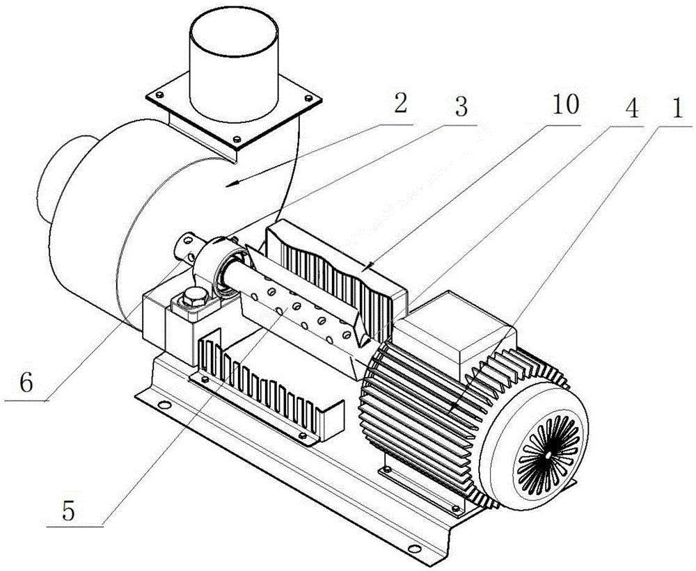
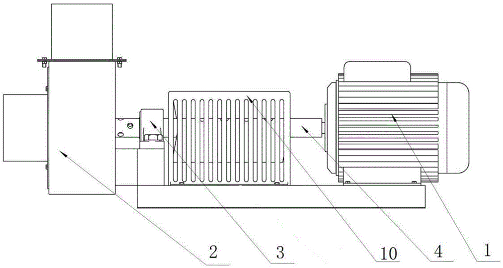
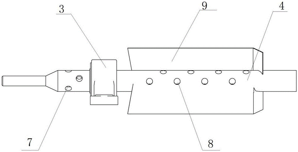
[0033] like figure 1 — Figure 7 Shown: a high temperature resistant fan is composed of a motor 1, an impeller device 2, a transmission shaft and a bearing seat 3 installed on the machine base. The transmission shaft is a hollow transmission shaft 4. The hollow transmission shaft 4 is hollow inside and on the shaft body. There are several air inlets 5 and air outlets 6, and the air outlet 6 is opened on the shaft wall near one end of the impeller device 2, and the hollow drive shaft 4 passes through the bearing seat 3 to connect the motor 1 and the impeller device 2, and the air outlet 6 is. The air outlet holes 7 are specifically distributed with 6 or 6 to 12 air outlet holes 7 in a plum blossom shape, and the air inlet ports 5 are 24 air inlet holes 8, and each 4 is a vertical row and is distributed in parallel on the hollow transmission shaft 4. On the axial surface, the hollow drive shaft 4 is provided with 2 or 2 to 4 pieces of wind turbine blades 9 and is symmetrically ...

Embodiment 2

[0036] like Figure 8 , Figure 9 , Figure 10 Shown: the air inlet 5 on the hollow drive shaft 4 in Example 1 is a long slot 11, the outer opening of the long slot 11 is larger than the inner opening, and the number of the long slot 11 There are two or more, such as four, the elongated slot 11 is parallel to the axis of the hollow transmission shaft 4, and the position of the elongated slot 11 is opened symmetrically with the axis as the axis, so there is no need to install it on the hollow transmission shaft 4 The tornado blades 9 and the safety protection cover 10 increase the air intake area of ​​the air inlet 5, thereby increasing the overall air intake volume, which can effectively improve the air intake rate, and can achieve cooling protection without the assistance of the tornado blades 9. The effect of the motor 1, and after the tornado blades 9 are canceled, the overall standardization of the fan is strong and beautiful, the working noise is low, and the safety and...


PUM


Abstract

The invention discloses a high-temperature-resistant draught fan. The high-temperature-resistant draught fan is composed of a motor, an impeller device, a transmission shaft and a bearing pedestal which are arranged on a machine base. The transmission shaft is a hollow transmission shaft. The hollow transmission shaft is hollow inside. A shaft body is provided with a plurality of air inlets and a plurality of air outlets. The air outlets are formed in the portion, close to one end of the impeller device, of the wall of the shaft body. The hollow transmission shaft penetrates the bearing pedestal to be connected with the motor and the impeller device. During work, the motor rotates to drive the hollow transmission shaft to rotate, air around the hollow transmission shaft enters the hollow transmission shaft from the air inlets in the rotating process and then flows out of the air outlets, gas flow circulation is formed through the whole hollow inner portion of the hollow transmission shaft in the process, and therefore heat on the transmission shaft is brought away, the cooling effect is achieved, the temperature transmitted to the motor can be low enough, and it can be avoided that the motor is damaged when the temperature exceeds the maximum temperature capable of being borne by the motor.

Description

technical field [0001] The invention relates to a blower, in particular to a blower with high temperature resistance effect, and belongs to the field of exhaust equipment. Background technique [0002] At present, the suction fan or blower used for stoves or stoves on the market is often because the connection shaft between the motor and the fan is short, and the flow of high-temperature gas in the fan impeller chamber makes the temperature of the impeller group too high, and the high temperature is transmitted from the transmission shaft. When the temperature of the motor is too high, it will cause damage to the motor and cause losses. Even if a fan is installed at the fan end, the cooling efficiency is low, the heat conduction speed is fast, and it is easy to burn the motor. The cost is too high, and the vibration is large during operation. SUMMARY OF THE INVENTION [0003] In view of the above-mentioned technical defects, the present invention provides a high-temperatu...

Claims


Application Information

Patent Timeline
IPC IPC(8): F04D25/08F04D29/58F04D29/053
CPCF04D25/082F04D29/053
Inventor 朱德征
Owner 朱德征
Why Eureka
Try Eureka