
Connecting structure for main shaft and gearbox of horizontal-axis wind turbine unit

A wind turbine and connection structure technology, applied in the direction of couplings, mechanical equipment, elastic couplings, etc., can solve the problem of improving the failure rate of wind turbine gearboxes and generators, high spindle strength requirements and manufacturing requirements, and high maintenance. Maintenance costs and other issues, to achieve the effect of improving stability and reliability, compact drive chain structure, and improving maintenance efficiency

Inactive Publication Date: 2016-04-06
SHANGHAI ELECTRIC WIND POWER GRP CO LTD +1
View PDF7 Cites 0 Cited by
  • Summary
  • Abstract
  • Description
  • Claims
  • Application Information

AI Technical Summary

Problems solved by technology

[0003] The structure of connecting the main shaft and the input shaft of the gearbox through the locking disc requires a long main shaft, and the entire engine room is lengthened; the main shaft has high strength requirements and manufacturing requirements; the main shaft bears complex forces, and the gearbox needs to bear a large additional load due to the influence of the main bearing structure. The stress situation is complicated
[0004] The main shaft and the input shaft of the gearbox are directly connected by bolts, the main shaft bears a large force, and the gearbox needs to bear the additional load caused by its own weight and deformation of the frame, and the stress situation is complicated
[0005] Larger loads and complex stress conditions can easily cause gearbox failures. At the same time, the dynamic additional loads on the generators connected to the gearboxes increase accordingly, which increases the failure rate of the gearboxes and generators of wind turbines, resulting in high costs. Maintenance and repair costs, and reduce equipment operating life

Method used


Image

  • Connecting structure for main shaft and gearbox of horizontal-axis wind turbine unit
  • Connecting structure for main shaft and gearbox of horizontal-axis wind turbine unit

Examples


Embodiment Construction

[0015] The present invention will be further described below in conjunction with accompanying drawing.

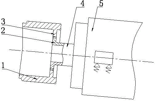
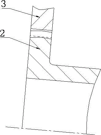
[0016] The figure shows a connection structure between the main shaft and the gearbox of a horizontal-axis wind turbine. In this structure, straight inner teeth (3) are machined on the main shaft (1), and drum-shaped outer teeth are machined on the input shaft (4) of the gearbox. The teeth (2), the main shaft (1) and the gearbox (5) realize the torque transmission through the complete meshing of the straight internal teeth (3) and the crowned external teeth (2).

[0017] Wherein, the straight tooth inner teeth (3) and the drum-shaped outer teeth (2) can be interchanged, that is, the drum-shaped outer teeth (2) are processed on the main shaft (1), and the gear box input shaft (4) The straight inner teeth (3) are processed on the top.

[0018] The straight internal teeth (3) can be directly machined on the main shaft (1) by installing a straight internal gear on the main sha...


PUM


Abstract

Provided is a connecting structure for a main shaft and a gearbox of a horizontal-axis wind turbine unit. Straight inner teeth are machined on the main shaft, drum-shaped outer teeth are machined on an input shaft of the gearbox, and torque transfer between the main shaft and the gearbox is achieved through complete engagement of the straight inner teeth and the drum-shaped outer teeth. The positions of the straight inner teeth can interchange with the positions of the drum-shaped outer teeth, and direct gear machining can be replaced by mounting corresponding gears. By the adoption of the flexible connection mode, a small quantity of radial and axial deviation and certain angular deviation of the axis of the main shaft and the axis of the input shaft of the gearbox are allowed. Stress of the main shaft, the gearbox and a main bearing between the main shaft and a main rack is simplified relatively, dynamic additional loads between the components are correspondingly reduced, the design and manufacturing requirements of the main shaft are lowered, the whole driving chain structure is more compact, and the design reliability of a wind turbine is improved. Meanwhile, the fault rate of the gearbox and the main bearing can be reduced, and the service life of the gearbox and the service life of the main bearing are prolonged. In addition, the structure is convenient to dismount and maintenance efficiency can be improved effectively.

Description

technical field [0001] The invention relates to a connection structure between a main shaft of a horizontal axis wind turbine and a gearbox. Background technique [0002] At present, the connection between the main shaft and the gearbox of the horizontal axis wind turbine at home and abroad adopts a rigid structure. Common forms include connecting the main shaft and the input shaft of the gearbox through a locking disc or directly connecting the main shaft and the input shaft of the gearbox through bolts and other structures. [0003] The structure of connecting the main shaft and the input shaft of the gearbox through the locking disc requires a long main shaft, and the entire engine room is lengthened; the main shaft has high strength requirements and manufacturing requirements; the main shaft bears complex forces, and the gearbox needs to bear a large additional load due to the influence of the main bearing structure. The stress situation is complicated. [0004] The mai...

Claims


Application Information

Patent Timeline
Patent Type & Authority Applications(China)
IPC IPC(8): F16D3/02
Inventor 沈鑫郭元超孙振军舒颖
Owner SHANGHAI ELECTRIC WIND POWER GRP CO LTD
Learn More