heat exchanger

A technology for condensers and subcoolers, which is applied in subcoolers, lighting and heating equipment, evaporators/condensers, etc., and can solve problems such as increasing the cost of condensers and systems

Active Publication Date: 2019-05-17
JOHNSON CONTROLS TECH CO +1
View PDF6 Cites 0 Cited by
  • Summary
  • Abstract
  • Description
  • Claims
  • Application Information

AI Technical Summary

Problems solved by technology

Since the refrigerant used for the liquid seal cannot be used on the system capacity, the huge amount of refrigerant liquid required to form the liquid seal will drive up the cost of the condenser and the system

Method used


Image

  • heat exchanger
  • heat exchanger
  • heat exchanger

Examples


Embodiment Construction

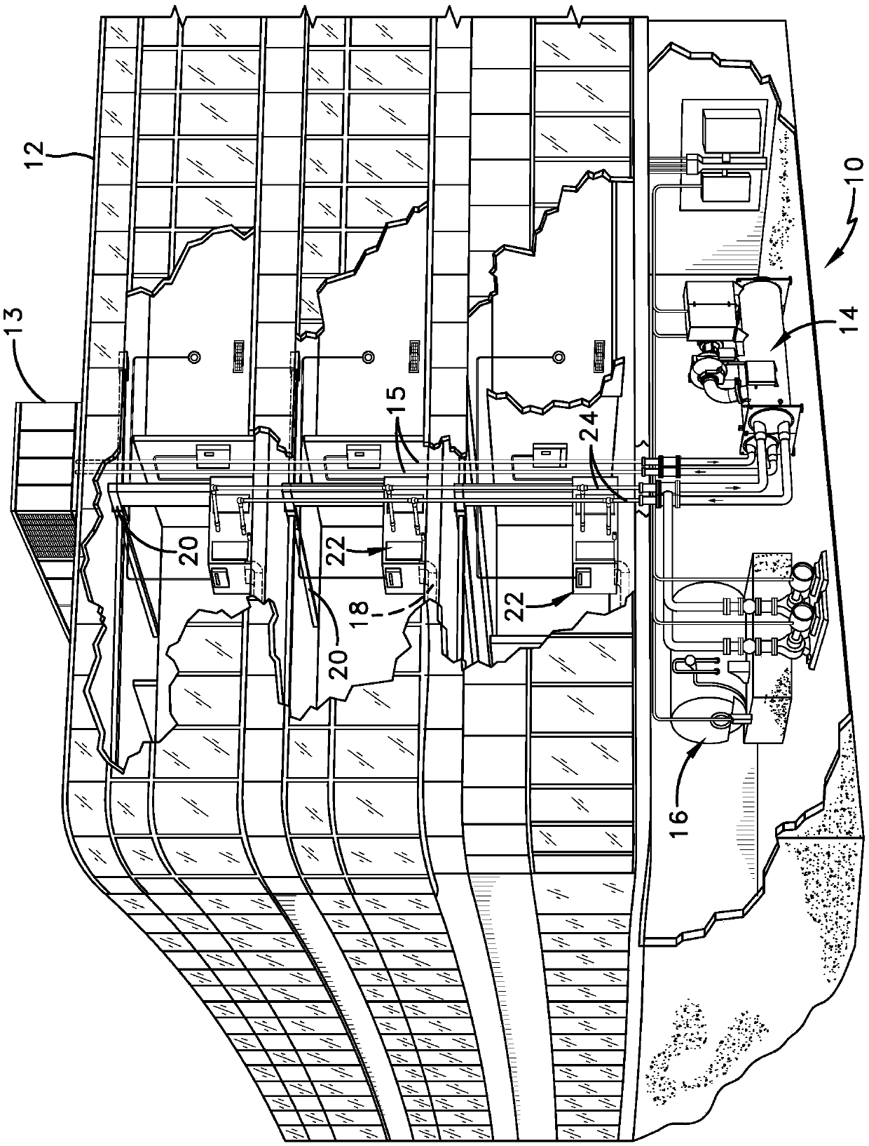
[0034] figure 1 One embodiment of a heating, ventilation, and air conditioning (HVAC) system 10 in a building 12 is shown in a typical commercial setting. The system 10 may include a vapor compression system 14 that can provide cooling liquid to cool the building 12 and a cooling tower 13 that provides a process fluid to the compression system 14 through a conduit 15. The system 10 may also include a boiler 16 that provides heated liquid to heat the building 12 and an air distribution system that circulates air through the building 12. The air distribution system may include a return air duct 18, an air supply duct 20 and an air handler 22. The air handler 22 may include a heat exchanger connected to the boiler 16 and the vapor compression system 14 through a conduit 24. The heat exchanger in the air handler 22 may receive the heated liquid from the boiler 16 and / or the cooled liquid from the vapor compression system 14, depending on the operating mode of the system 10. In on...


PUM


Abstract

A condenser includes a shell with a vapor refrigerant inlet, a first tube bundle, and a liquid refrigerant outlet. A second tube bundle is positioned in the subcooler section. The subcooler component has a central channel and at least two outer channels and is fitted to the housing.

Description

[0001] Cross-reference of related applications [0002] This application is a partial continuation application of US application No. 12 / 809,839 entitled "HEAT EXCHANGER" with the filing date or 371(c) dated June 21, 2010, which was filed on January 2, 2009 The national phase of the international application No. PCT / US2009 / 030027 with the title "HEAT EXCHANGER", which requires the United States provisional application No. 61 / 018,539 filed on January 2, 2008 and titled "CONDENSER SUBCOOLER" All these applications are incorporated into this application by reference. Background technique [0003] This application relates generally to heat exchangers in vapor compression systems. The present application relates more specifically to condensers for vapor compression systems with subcooler components. [0004] In some condensers, the tube bundle(s) can be positioned in the housing or shell and used to circulate a fluid capable of exchanging heat with refrigerant vapor entering the housing....

Claims


Application Information

Patent Timeline
Patent Type & Authority Patents(China)
IPC IPC(8): F25B39/04F25B40/02
Inventor 王生龙苏秀平胡洪明M·R·伯德尔二世A·M·韦尔奇
Owner JOHNSON CONTROLS TECH CO
Why Eureka
Try Eureka