Wristband type infrared thermal imaging device
An infrared thermal imaging and wristband-type technology, applied in the wristband field, can solve the problems of affecting the wearing comfort of the helmet, unbalanced head load, immature design of the display part of the helmet-type thermal imaging device, etc.
- Summary
- Abstract
- Description
- Claims
- Application Information
AI Technical Summary
Problems solved by technology
Method used
Image
Examples
no. 1 Embodiment approach
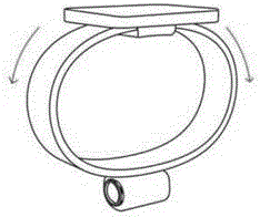
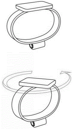
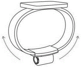
[0014] First, a first embodiment of the present invention will be described. figure 1 It shows a wrist-worn infrared thermal imaging device as various embodiments of the present invention, figure 1 The thermal imaging device has: infrared thermal image display part 1, infrared thermal image acquisition part 2, wristband main body 3.
[0015] The infrared thermal image display unit 1 is mainly composed of a liquid crystal display screen (not shown), which mainly plays the role of display. The display effect can be selected from LCD liquid crystal display, OLED liquid crystal display or other forms of display screens according to needs.
[0016] The infrared thermal image acquiring unit 2 is composed of an unshown optical imaging component, an infrared core, and the like. The optics consist of an infrared optical lens for focusing the received infrared radiation onto the infrared detector. The infrared core is composed of a detector and a signal processing circuit. The detect...
no. 2 Embodiment approach
[0020] Embodiment 2 of the present invention is to illustrate that the relative installation positions of the infrared thermal image display unit 1 and the infrared thermal image acquisition unit 2 can be set according to requirements and usage habits.
[0021] like figure 2 As shown, the installation positions of the infrared thermal image display unit 1 and the infrared thermal image acquisition unit 2 on the wristband main body can be in the same direction of the wristband main body. preferred, such as image 3 , when in the same direction, the infrared thermal image display unit 1 and the infrared thermal image acquisition unit 2 can be integrated into one module.
[0022] like Figure 4 As shown, the installation positions of the infrared thermal image display unit 1 and the infrared thermal image acquisition unit 2 on the wristband main body can also be in different directions of the wristband main body.
no. 3 Embodiment approach
[0024] Embodiment 3 of the present invention illustrates that the positions and angles of the infrared thermal image display unit 1 and the infrared thermal image acquisition unit 2 can be adjusted according to requirements.
[0025] like Figure 5-1 , Figure 5-2 As shown, the infrared thermal image display part 1 can slide and / or adjust the angle on the strap main body, and the infrared thermal image acquisition part 2 is fixed.
[0026] like Figure 6-1 , Figure 6-2 As shown, the infrared thermal image acquisition part 2 can slide and / or adjust the angle on the strap main body, and the infrared thermal image display part 1 is fixed.
[0027] like Figure 7-1 , Figure 7-2 As shown, both the infrared thermal image display part 1 and the infrared thermal image acquisition part 2 can be slid on the strap main body or adjusted in angle.
PUM
 Abstract
Description
Claims
Application Information
 - R&D
- Intellectual Property
- Life Sciences
- Materials
- Tech Scout
- Unparalleled Data Quality
- Higher Quality Content
- 60% Fewer Hallucinations
Browse by: Latest US Patents, China's latest patents, Technical Efficacy Thesaurus, Application Domain, Technology Topic, Popular Technical Reports.
© 2025 PatSnap. All rights reserved.Legal|Privacy policy|Modern Slavery Act Transparency Statement|Sitemap|About US| Contact US: help@patsnap.com


