
Method for measuring large power CO2 laser divergence angle

A high-power, divergence-angle technology, applied in the direction of testing optical properties, can solve problems such as the inability to accurately measure the divergence angle of high-power lasers, and achieve the effects of avoiding damage, accurate measurement results, and simple test equipment

Active Publication Date: 2016-04-06
CHANGCHUN INST OF OPTICS FINE MECHANICS & PHYSICS CHINESE ACAD OF SCI
View PDF6 Cites 7 Cited by
  • Summary
  • Abstract
  • Description
  • Claims
  • Application Information

AI Technical Summary

Problems solved by technology

[0005] In order to solve the problem that the existing measurement method cannot accurately measure high-power CO 2 To solve the problem of laser divergence angle, provide a method based on infrared imaging to identify laser spots to measure high-power CO 2 Laser Divergence Method

Method used


Image

  • Method for measuring large power CO2 laser divergence angle

Examples


Embodiment

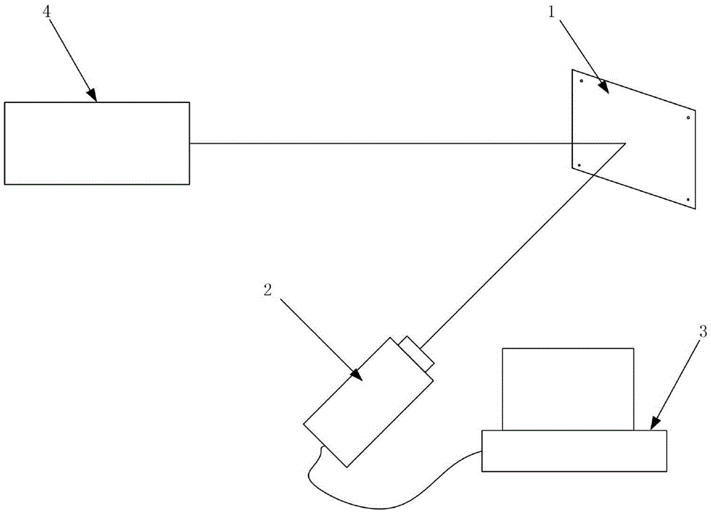
[0028] Will be tested high-power CO 2 The laser 4 is fixed, along the direction of the optical axis in the same direction as the high-power CO to be measured 2 The diffuse reflection plate 1 is fixed at a distance of 70m from the laser 4. According to the theoretically calculated divergence angle and the diameter of the laser exit spot, the laser spot formed after the laser transmits this distance can all fall in the diffuse reflection plate 1, and the diffuse reflection plate is blocked by a refractory material. 1 and pre-receive the laser spot, adjust the height of the diffuse reflection plate 1 according to the received laser spot position, so that the laser spot position is in the center of the diffuse reflection plate 1.

[0029] Place an infrared imaging device 2 (the focal length of the infrared imaging device is 15 m) at a distance of 15 m away from the optical axis of the laser and at a distance of 15 m from the diffuse reflection plate 1, and fine-tune the infrared i...


PUM


Abstract

The invention discloses a method for measuring a large power CO2 laser divergence angle, and belongs to the large power CO2 laser technology field. In order to solve the problem of measuring the large power CO2 laser divergence angle accurately in prior art, a large power CO2 laser to be measured is fixed; a diffuse reflection board is arranged vertical to the direction of an optical axis of the laser to be measured to make a laser light spot at the center of the diffuse reflection board; four black bodies are arranged at the four drift angles of the diffuse reflection boards to keep the diffuse reflection board powered on and make the black bodies hot; then, an infrared imaging device is installed in a way that a certain angle is formed between the infrared imaging device and the incidence plane of the diffuse reflection board and the distance is the focal length of the infrared imaging device; finally, the infrared imaging device is connected with a computer; the large power CO2 laser to be measured emits laser continuously; then, the infrared imaging device is closed; the laser emission is stopped, at the same time, the infrared imaging device is started; the image generated after the diffuse reflection board being irradiated by the laser is collected; the image data is transmitted to the computer; and the laser divergence angle of the large power CO2 laser is calculated by the computer.

Description

technical field [0001] The invention relates to a method for measuring high-power CO 2 The method of laser divergence angle belongs to high power CO 2 field of laser technology. Background technique [0002] high power CO 2 Lasers are widely used in many fields such as industry, medical treatment, military and scientific research. In recent years, high-power CO 2 Laser far-field applications are developing rapidly, and the distribution of far-field spots directly determines the effect of laser. The far-field spot is affected by the laser divergence angle, so the laser divergence angle is an important indicator to measure the effect of the laser. The intuitive manifestation of the laser divergence angle is the change of the laser spot size due to the change of the laser transmission distance. To measure the laser divergence angle, the laser spot size must be accurately obtained. [0003] The spot ablation method is a relatively common high-power laser divergence angle ...

Claims


Application Information

Patent Timeline
Patent Type & Authority Applications(China)
IPC IPC(8): G01M11/02
CPCG01M11/02
Inventor 张阔陈飞杨贵龙邵春雷郭劲
Owner CHANGCHUN INST OF OPTICS FINE MECHANICS & PHYSICS CHINESE ACAD OF SCI
Learn More