SOT23 lead frame and packaging process flow thereof

A technology of SOT23 and lead frame, applied in the field of SOT23 lead frame and its packaging process, can solve the problems of multi-area, middle-rib area and gap waste between adjacent two outer pins, low frame utilization rate, etc. The effect of improving efficiency and improving utilization

Active Publication Date: 2016-04-06
CHINA CHIPPACKING TECH
View PDF4 Cites 6 Cited by
  • Summary
  • Abstract
  • Description
  • Claims
  • Application Information

AI Technical Summary

Problems solved by technology

like figure 1 As shown, the SOT23 lead frame structure includes a frame A, a plurality of installation units B and flow channels C arranged on the frame, each installation unit includes a base island and pins arranged on the upper and lower sides of the base island, and each pin Including the outer pins and inner pins, in the traditional SOT23 lead frame structure, the outer pins of the two adjacent installation units are aligned up and down and spaced apart from each other, and the spaced parts are formed as middle ribs D, so that the outer pins The area of ​​the middle rib between the outer pins and the gap between two adjacent outer pins is wasted, so the utilization rate of the frame is low; and every other column of installation unit B is provided with a column of flow channels C, that is, when plastic sealing Only one product can be plastic-sealed at a time, so more runners C must be set on the frame A to meet the demand, and more runners C will occupy more area, thereby reducing the utilization rate of the frame and causing the mold compound low utilization

Method used


Image

  • SOT23 lead frame and packaging process flow thereof
  • SOT23 lead frame and packaging process flow thereof
  • SOT23 lead frame and packaging process flow thereof

Examples


Embodiment Construction

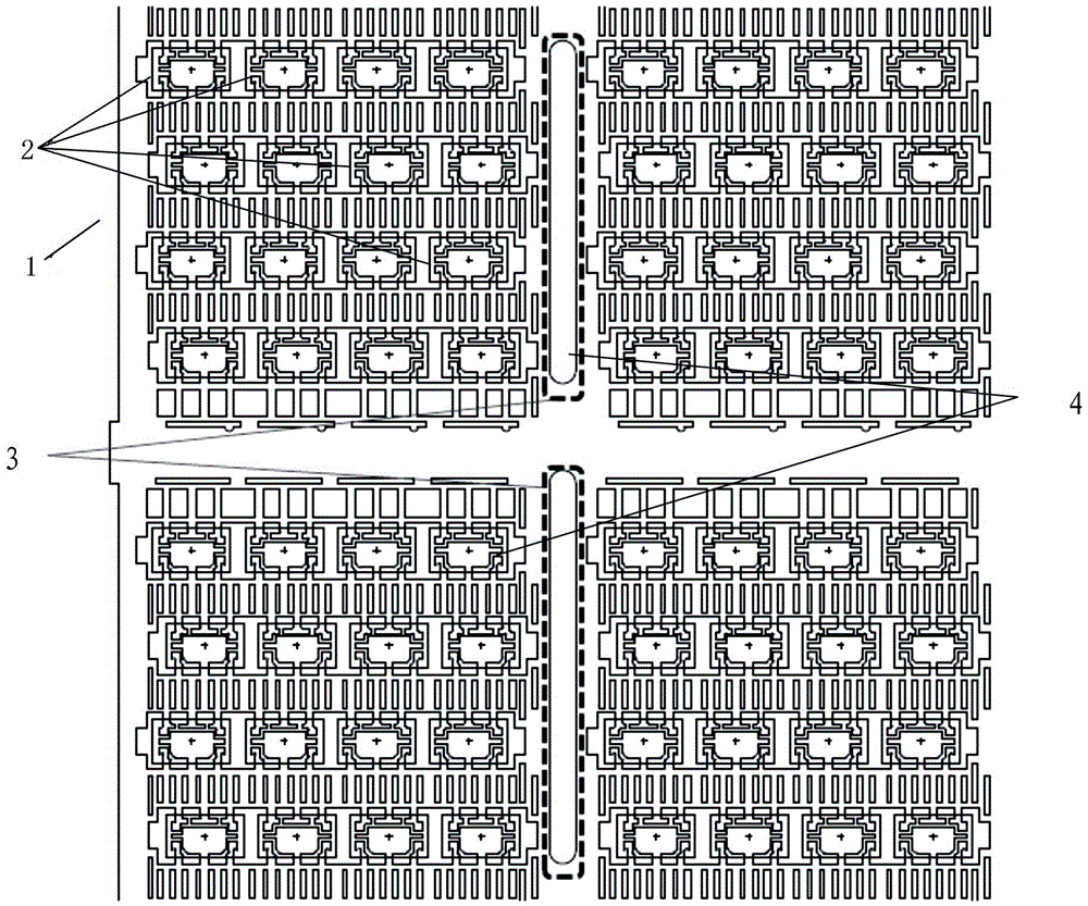
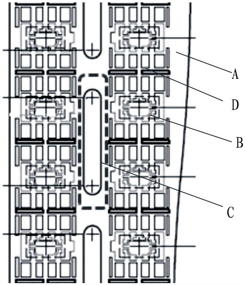
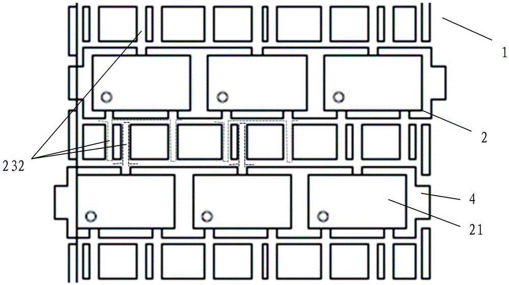
[0036] like Figures 2 to 15 As shown, the SOT23 lead frame structure of the present invention includes a frame 1, a plurality of installation units 2 arranged on the frame 1, and each installation unit 2 includes a base island 21, and leads arranged on two opposite sides of the base island 21. pins 23, each of which pins 23 includes inner pins 231 (as Figure 8 As shown) and outer pins 232, the plurality of installation units 2 are arranged on the frame 1 in X rows and XY columns, and the outer pins 232 of two adjacent rows of installation units 2 are arranged to cross and stagger each other, and A column of runners 3 is provided for every N rows of installation units 2 on the frame 1, and the N is not less than 2. The installation unit 2 close to the runners 3 is provided with a glue injection port 4 on the side facing the runners 3. A dambar-5 is arranged between two adjacent outer pins 232 of the same installation unit 2, and a dambar-6 is arranged between adjacent outer ...


PUM


Abstract

The invention discloses an SOT23 lead frame structure and a packaging process flow thereof. The SOT23 lead frame structure comprises a frame and a plurality of mounting units, wherein the mounting units are arranged on the frame in a manner of X rows and XY columns; a column of runners is arranged at an interval of N columns of mounting units; N is not smaller than 2; each mounting unit comprises an outer pin; the outer pins of two adjacent rows of mounting units are crosswire staggered with one another; a dam bar I is arranged between two adjacent outer pins of the same mounting unit; a dam bar II is arranged between the adjacent outer pins of two adjacent mounting units in the same row of mounting units; a dam bar III is arranged between the outer pins at the outermost sides of the mounting units at the left end and the right end in the same row of mounting units and the frame; and in trimming and forming processes, the dam bar I at one side is firstly cut, the dam bar I at the other side is cut and conveyed to a track of a forming part, and then the dam bar II and the dam bar III are cut off.

Description

technical field [0001] The invention relates to an integrated circuit package lead frame, in particular to an SOT23 lead frame and its packaging process flow. Background technique [0002] Chip packaging is a technology that packs integrated circuits with insulating plastic or ceramic materials. It not only plays the role of placing, fixing, sealing, protecting chips and enhancing thermal conductivity, but also serves as a bridge between the internal world of the chip and the external circuit. Small Outline Transistor package (SOT23, SmallOutlineTransistor) is a small SMT chip package commonly used at present. like figure 1 As shown, the SOT23 lead frame structure includes a frame A, a plurality of installation units B and flow channels C arranged on the frame, each installation unit includes a base island and pins arranged on the upper and lower sides of the base island, and each pin Including the outer pins and inner pins, in the traditional SOT23 lead frame structure, t...

Claims


Application Information

Patent Timeline
Patent Type & Authority Applications(China)
IPC IPC(8): H01L23/495H01L21/56
CPCH01L21/56H01L23/49541H01L2224/97
Inventor 梁大钟刘兴波宋波石艳
Owner CHINA CHIPPACKING TECH
Why Eureka
Try Eureka