
Electronic connector

A technology of electronic connectors and connectors, applied in the direction of connection, fixed connection, parts of connection devices, etc., can solve problems such as incompetence

Inactive Publication Date: 2016-04-06
KUANG YING COMPUTER EQUIP CO LTD
View PDF6 Cites 3 Cited by
  • Summary
  • Abstract
  • Description
  • Claims
  • Application Information

AI Technical Summary

Problems solved by technology

[0003] However, the above-mentioned improvements are only limited to the USB2.0 specification. Nowadays, technology is changing with each passing day, and it can be said that it is improving every day. Connectors such as USB2.0, USB3.0, Type-A, Type-B, etc. The upgrade of hardware or the advancement of hardware specifications must evolve with the changes of the times. Unfortunately, the above-mentioned two-way plug-in connector is only suitable for USB2.0, and it is not suitable for more advanced connectors.

Method used


Image

  • Electronic connector
  • Electronic connector
  • Electronic connector

Examples


Embodiment Construction

[0072] In order to achieve the above-mentioned purpose and effect, the technical means and the structure adopted by the present invention are hereby described in detail with respect to the preferred embodiments of the present invention.

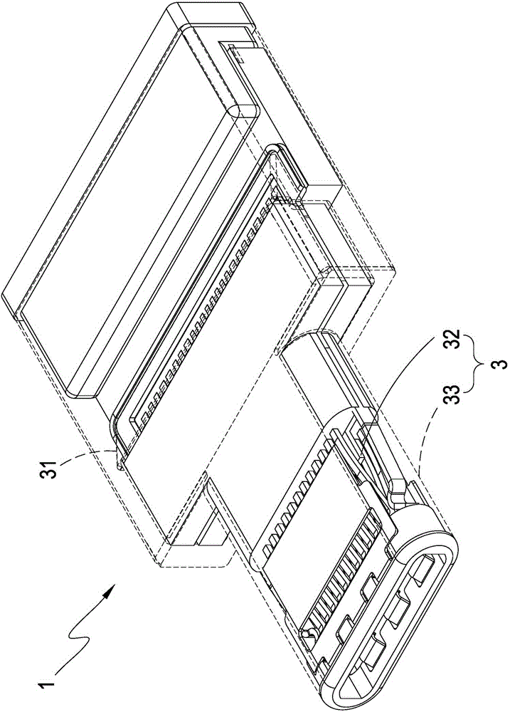
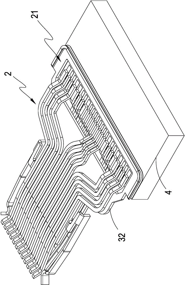
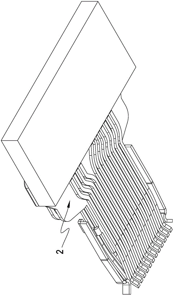
[0073] see figure 1 , figure 2 and image 3 As shown, it is a perspective view of a preferred embodiment of the present invention, a perspective view of double-row pins and a perspective view of another angle of double-row pins. It can be clearly seen from the figure that the electronic connector 1 of the present invention includes:

[0074] A transmission conductor set 2 with double rows of elastic contact parts for forward and reverse plugging into the connector socket;

[0075] A set of transmission conductor pins 21 defined in the rear end of the transmission conductor set 2 and arranged in a single row;

[0076] a circuit substrate 4 electrically connected to the transmission conductor pin group 21;

[0077] A shielding case 3 for a...


PUM


Abstract

The invention relates to an electronic connector. The structure of the electronic connector mainly comprises a transmission conductor group having two-row flexible contact parts for forward / reverse insertion to a connector female socket, a transmission conductor pin group defined at the rear end of the transmission conductor group in a single-row arrangement, a circuit board electrically connected to the transmission conductor pin group, a shielding shell body for accommodating the transmission conductor group, and an oblique cover part formed by extending from the shielding shell body and used for shielding the transmission conductor pin group. By adopting the structure, the contact parts of the connector transmission conductor group are configured in a two-row arrangement manner, thus a male joint and a female seat can be abutted in an omnidirectional manner, and both forward and reverse insertion are allowed. The transmission conductor group is extended backward to form the transmission conductor pin group which is in a single-row arrangement, thus convenience of production process is reserved, such that both the production side and client side can benefit from the advantages of the electronic connector, and the oblique cover part shields the transmission conductor pin group to reduce noise interference of EMI, RFI and the like.

Description

technical field [0001] The present invention provides an electronic connector, which is applied to data processing equipment, especially refers to a type that can be plugged into the connector socket in both forward and reverse directions, and the pin ends are kept on the same side of the circuit board for single-row welding. An electronic connector that is both convenient in process and use. Background technique [0002] According to the prosperity of the electronic industry, almost all electronic products have the demand for the use of connectors, and the most widely used Universal Serial Bus (Universal Serial Bus, USB) on the market is the connector standard interface specification formulated by the association. This specification is Recently, it is the most widely used on the market. Therefore, there are many improvements derived from this type of connector. Among them, the simplest but most convenient improvement is the two-way insertion of the connector. Due to the do...

Claims


Application Information

Patent Timeline
IPC IPC(8): H01R13/02H01R13/6585H01R13/6581H01R12/55
Inventor 钟轩禾林昱宏
Owner KUANG YING COMPUTER EQUIP CO LTD
Learn More