Automatic production equipment for FPC connectors

An automatic production and connector technology, which is applied in the direction of connection, assembly/disassembly of contacts, circuit/collector parts, etc., can solve the problems of high difficulty in manual assembly, low product qualification rate, and low efficiency of FPC connectors

Inactive Publication Date: 2016-04-06
SHENZHEN YANFENG SCI & TECH
4 Cites 30 Cited by

AI-Extracted Technical Summary

Problems solved by technology

[0003] In order to overcome the deficiencies of the prior art, the present invention provides an automatic production equipment for FPC connectors, which solves the techn...

Method used

Preferably, the product vibration conveying mechanism one 11, the main body pin precise pushing mechanism one 12, the front terminal insertion mechanism 13, the product vibration conveying mechanism two 14, the main body pin precise pushing mechanism two 15, the rear terminal insertion Mechanism 16, product vibration conveying mechanism 3 17, product separation and conveying mechanism 18, product front terminal flattening mechanism 19, product rear terminal flattening mechanism 20, product withstand voltage detection mechanism 21, product cover installation mechanism 22, product front terminal repress Flat mechanism 23, main body soldering tab precise positioning mechanism 1 24, product left soldering tab insertion mechanism 25, main body soldering tab precise positioning mechanism 2 26, product right soldering tab insertion mechanism 27, CCD detection mechanism 28, laser marking mechanism 29 , the product NG removal mechanism 30 and the product packaging mechanism 31 are all provided with the above-mentioned photoelectric control module and wireless control module. The photoelectric control module realizes photoelectric control through various photoelectric sensors and supporting devices, and the installation position, quantity and type of various sensors can be selected according to the needs in the implementation process. The wireless control module cooperates with the wireless control software to perform wireless control on the entire device through various data from various sensors, such as remote wireless control, remote mobile phone control, etc., with a high degree of automation and intelligence, and is very suitable for large-scale intelligent ,Automated manufacturing.
The plastic main body is transported to the first guide rail 121 for pushing the pins of the main body through the product vibration mechanism-11, wherein the first guide rail 121 for pushing the pins of the main body is 2 mm higher than the second guide rail 123 for pushing the pins of the main body, and passes through the main body in the middle of the two The pin pushing and lifting mechanism changes the continuo...

Abstract

The invention discloses automatic production equipment for FPC connectors. The automatic production equipment for FPC connectors is characterized by comprising a first product vibratory conveying mechanism, a first main body pin accurate pushing mechanism, a front terminal inserting mechanism, a second product vibratory conveying mechanism, a second main body pin accurate pushing mechanism, a rear terminal inserting mechanism, a third product vibratory conveying mechanism, a product separating and carrying mechanism, a product front terminal flattening mechanism, a product rear terminal flattening mechanism, a product withstand voltage detecting mechanism, a product cover mounting mechanism, a product front terminal re-flattening mechanism, a first main body socket welding pad accurate positioning mechanism, a product left welding pad inserting mechanism, a second main body socket welding pad accurate positioning mechanism, a product right welding pad inserting mechanism, a CCD detecting mechanism, a laser marking mechanism, a product NG eliminating mechanism and a product packaging mechanism. The automatic production equipment for FPC connectors has the advantages of high automation degree, high work efficiency, good product quality, high product percent of pass, capability of saving human resources and the like which do not exist in the prior art.

Application Domain

Contact member assembly/disassembly

Technology Topic

Process engineeringManufacturing engineering +2

Image

  • Automatic production equipment for FPC connectors
  • Automatic production equipment for FPC connectors
  • Automatic production equipment for FPC connectors

Examples

  • Experimental program(1)

Example Embodiment

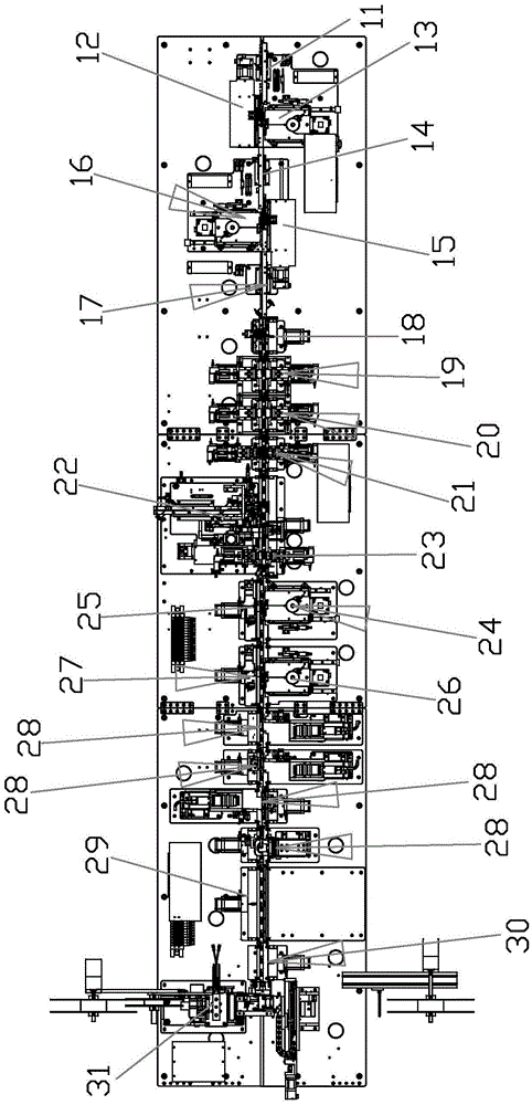
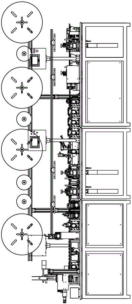
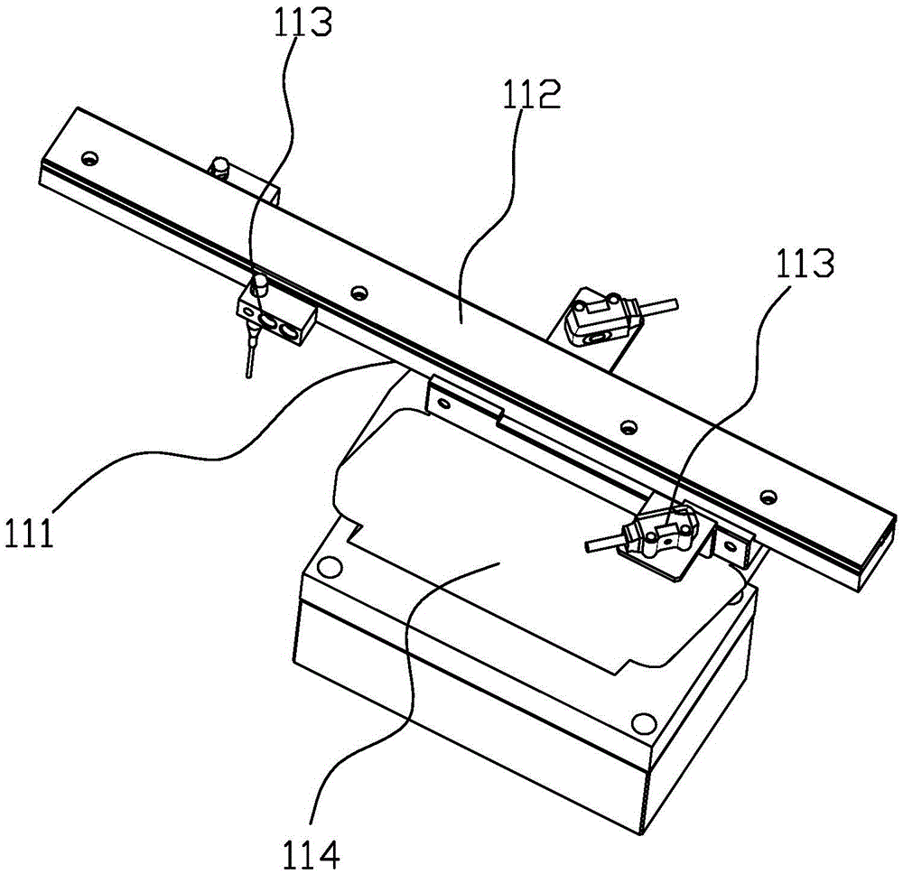
[0118] The idea, specific structure and technical effects of the present invention will be clearly and completely described below in conjunction with the embodiments and accompanying drawings, so as to fully understand the purpose, features and effects of the present invention. Apparently, the described embodiments are only some of the embodiments of the present invention, rather than all of them. Based on the embodiments of the present invention, other embodiments obtained by those skilled in the art without creative efforts belong to The protection scope of the present invention. In addition, all the connection/connection relationships involved in the patent do not simply refer to the direct connection of components, but mean that a better connection structure can be formed by adding or reducing connection accessories according to specific implementation conditions. The various technical features in the invention can be combined interactively on the premise of not contradicting each other. Figure 1-66.
[0119] Specific reference figure 1 , figure 2 , an automatic production equipment for FPC connectors, including a product vibration conveying mechanism 11, a main body pin precise pushing mechanism 12, a front terminal insertion mechanism 13, a product vibration conveying mechanism 2 14, a main body pin precise pushing mechanism 15, and a rear Terminal insertion mechanism 16, product vibration conveying mechanism 3 17, product separation and conveying mechanism 18, product front terminal flattening mechanism 19, product rear terminal flattening mechanism 20, product withstand voltage detection mechanism 21, product cover installation mechanism 22, product front terminal Re-flattening mechanism 23, main body soldering tab precise positioning mechanism 1 24, product left soldering tab insertion mechanism 25, main body soldering tab precise positioning mechanism 2 26, product right soldering tab insertion mechanism 27, CCD detection mechanism 28, laser marking Mechanism 29, product NG removal mechanism 30 and product packaging mechanism 31.
[0120] The semi-finished main body plastic of the product enters the product vibration conveying mechanism 11 through the vibrating plate, and is conveyed to the main pin pin precision pushing mechanism 12 through the linear vibration of the mechanism. After the initial position of the plastic body is set by the mechanism, the front terminal insertion mechanism 13 inserts the terminal. The 1PCS terminal mechanism pushes the plastic body forward by 0.6mm until the set number of terminals is inserted, and then the pushing part of the mechanism returns to the original point to prepare for the next pin insertion action of the plastic body. The semi-finished product with the front terminal plugged is sent to the product vibration conveying mechanism 214, and is conveyed by linear vibration to reach the main pin pin precision pushing mechanism 215 for the post-insertion terminal process. The process here is the same as the pre-insertion terminal process. After the terminal is finished, the semi-finished product is transported to the product vibration conveying mechanism 3 17, and the product reaches the product separation conveying mechanism 18 through linear vibration conveying, and the mechanism changes the semi-finished product from linear vibration continuous conveying to equal-step separated conveying (that is, products are conveyed one by one. Next to the conveying, the products are separated by a certain distance and conveyed one by one, in order to complete the follow-up process), the semi-finished product is transported to the product front terminal flattening mechanism 19 by the mechanism, and the flattening process of the front terminal is carried out (because the terminal insertion process cannot guarantee each The insertion depth of the terminal is completely consistent), and the front terminal is flattened and then transported to the rear terminal flattening mechanism 20 of the product for the rear terminal flattening process.
[0121] refer to image 3 , preferably, the product vibration mechanism 11 includes a vibrating conveying rail 111, a vibrating rail cover 112 arranged on the vibrating conveying rail 111 and vibrating rail sensors 113 arranged at both ends of the vibrating conveying rail 111, the The vibrating transport rail 111 is mounted on a vibrator 114 .
[0122] refer to Figure 4 , Figure 5 , preferably, the main body pin precise pushing mechanism 12 includes a main body pin pushing first guide rail 121 with a height difference, a pushing first guide rail cover 122, a main body pin pushing second guide rail 123, and a pushing second guide rail cover Plate 124, the main body pin pushing elevating mechanism arranged between the main body pin pushing first guide rail 121 and the main body pin pushing second guide rail 123, the main body pin pushing elevating mechanism includes the main body pin pushing third guide rail 125. Push the third guide rail cover plate 126, the push mechanism slide block 127, and push the push slide block drive motor 128 that pushes the push mechanism slide block 127 to slide.
[0123] The plastic body is transported to the first guide rail 121 for pushing the pins of the main body through the product vibration mechanism 11. The first guide rail 121 for pushing the pins of the main body is 2 mm higher than the second guide rail 123 for pushing the pins of the main body. The lifting mechanism changes the continuously conveyed plastic body into a single conveyance by the push claws to complete pin positioning and push. When the plastic main body passes through the channel formed by the main body pin pushing the first guide rail 121 and pushing the first guide rail cover plate 122 into the channel formed by the main body pin pushing the third guide rail 125 and pushing the third guide rail cover plate 126, the optical fiber sensor detects the plastic main body Enter, push the slider drive motor 128 to act accordingly, drive the push mechanism slider 12 to move down 2mm, make the plastic main body align with the main body pin and push the channel formed by the second guide rail 123 and the second guide rail cover plate 124; the first push Claw 1291 (the servo motor drives the screw for precise movement) pushes the plastic body to the pin insertion position for pin insertion preparation. After each 1PCS terminal is inserted, the push claw pushes forward 0.6mm (this distance can be set according to different products) Different numerical values) to complete the insertion of the next terminal until the set number of terminals is inserted; then the second push claw 1292 then pushes, and the first push claw 1291 returns to the origin. The two push claws reciprocate in a circular motion, reducing the waiting time for the push action.
[0124] refer to Image 6 , the front terminal insertion mechanism 13 includes a cam mechanism 131 , a cam-follower terminal insertion mechanism 132 and a terminal feeding mechanism 133 .
[0125] refer to Figure 7 , preferably, the cam mechanism 1 includes a cam installation main shaft 1311 and an upper cam 1312 and a lower cam 1313 arranged on the cam installation main shaft 1311, and also includes a cam mechanism driving device 1314 for driving the cam installation main shaft 1311 to rotate, The cam mechanism driving device 1314 drives the cam installation main shaft 1311 to rotate through a pulley device.
[0126] Preferably, the pulley device includes a first pulley 1315 arranged on the cam installation main shaft 1311, a second pulley 1316 arranged at the output end of the cam mechanism driving device 1314, and a Belt 1317.
[0127] refer to Figure 10 , Figure 11 , preferably, the cam follower terminal insertion mechanism 132 includes a right swing arm assembly 1321, a left swing arm assembly 1322, a pre-insert assembly 1323 and an inserted in-position assembly 1324, and the right swing arm assembly 1321, the pre-insert assembly 1323 and the lower The cam 1313 is linked, and the left swing arm assembly 1322 , the insertion-in-place assembly 1324 and the upper cam 1312 are linked.
[0128] Among them, the right swing arm group 1321 completes the clamping action, the left swing arm assembly 1322 completes the cutting action, the pre-insertion assembly 1323 completes the pre-insertion action, and the insertion-in-place assembly 1324 completes the insertion-in-place action.
[0129] refer to Figure 8 , Figure 9 , preferably, the upper cam 1312 includes a first cam groove 13121 and a second cam groove 13122 , and the lower cam 1313 includes a third cam groove 13131 and a fourth cam groove 13132 .
[0130] refer to Figure 12-14 , the right swing arm assembly 1321 includes a right swing arm 13211 hingedly fixed at its middle position, a right swing arm follower bearing 13212 is installed at one end of the right swing arm 13211, and a clamping workpiece 13213 is installed at the other end of the right swing arm 13211 And positioning pin 13214, the right swing arm driven bearing 13212 is placed in the third cam groove 13131 of the lower cam 1313 and the movement track of the right swing arm 13211 is controlled by the running track of the lower cam 1313.
[0131] When the lower convex 1313 wheel rotates, the right swing arm bearing 13212 will drive the clamping workpiece 13213 and positioning pin 13214 of the head through the swing arm to make a designed forward and backward movement in the direction of the arrow; the positioning pin 13214 is used to fix the terminal. Location.
[0132] refer to Figure 15-17 , preferably, the left swing arm assembly 1322 includes a left swing arm 13221 hingedly fixed at its middle position, one end of the left swing arm 13221 is installed with a left swing arm driven bearing 13222, and the other end of the left swing arm 13221 is installed There is a workpiece 13223 for clamping and cutting. The driven bearing 13222 of the left swing arm is placed in the first cam groove 13121 of the upper cam 1312 and the trajectory of the left swing arm 13221 is controlled by the trajectory of the upper cam 1312 .
[0133] The left swing arm driven bearing 13222 is placed in the first cam groove 13121 of the upper cam 1312. When the upper cam 1312 rotates, the left swing arm driven bearing 13222 will drive the head to clamp and cut off the workpiece 13223 through the swing arm Make designed forward and backward movements in the direction of the arrow.
[0134] refer to Figure 18-21 , preferably, the pre-insertion component 1323 includes a pre-insertion fixing seat 13231, a clamping guide rail 13232 and a clamping guide rail cover 13233, and the part of the right swing arm component 1321 and the left swing arm component 1322 for clamping terminals It can slide in the sliding space formed by the clamping guide rail 13232 and the clamping guide rail cover plate 13233. The pre-insertion fixing seat 13231 has a chute, and a pre-insertion slider 13234 is installed in the chute. The pre-insertion slider One end of 13234 is fixed with cutter 13235, and the other end of pre-inserted slider 13235 is installed with pre-inserted driven bearing 13236, and said pre-inserted driven bearing 13236 is placed in the fourth cam groove 13132 of lower cam 1313 and is driven by The running trajectory of 1313 controls the pre-insertion slider 13235 to move back and forth in the chute of the pre-insertion fixing seat 13234 .
[0135] When the pre-insertion slider 13235 slides back and forth in the groove of the pre-insertion holder 13231 under the drive of the lower cam 1313, it will drive the cover plate 13233, the guide rail 13232, the cutter 13235, the clamping workpiece 13213 and the clamping and cutting workpiece 13223 forward The motion completes the pre-insertion action of the terminal.
[0136] The pre-insertion driven bearing 13236 is placed in the first cam groove 13132 of the lower cam 1313. When the cam rotates, the pre-insertion driven bearing 13236 will drive the pre-insertion slider 13234 to move back and forth.
[0137] refer to Figure 22 , 23 , preferably, the insertion-in-position component 1324 includes an insertion-in-position slider 13241, the pre-insertion slider 13234 is provided with a chute, and the insertion-in-position slider 13241 is placed in the chute of the pre-insertion slider 13234 One end of the inserted slider 13241 is fixed with an inserted thimble 13242, and the other end of the inserted slider 13241 is installed with an inserted driven bearing 13243, and the inserted driven bearing 13243 is placed in the second cam groove of the upper cam 1312 13122 and is inserted into the position slide block 13241 to move back and forth in the chute of the pre-inserted slide block 13234 by the running track control of the upper cam 1312.
[0138] The sliding block 13241 inserted in place moves in the groove of the pre-inserted sliding block 13234 . The inserted thimble 13242 moves in the slot of the thimble holder and the cutter 13235 .
[0139] The inserted driven bearing 13243 is placed in the second cam groove 13122 of the upper cam 1312. When the cam rotates, the inserted driven bearing 13243 will drive the inserted slider 13241 to move back and forth, driving the inserted thimble 13242 to complete the terminal insertion Action in place.
[0140] Figure 25 Schematic diagram for the terminal insertion process:
[0141] Step 1: the clamping workpiece 13213 is first moved to the left to the end surface of the terminal workpiece 134;
[0142] Step 2: Then clamp and cut off the workpiece 13223 and move right to the end face of the terminal workpiece 134;
[0143] Step 3: Clamp and cut off the workpiece 13223 and clamp the workpiece 13213 to clamp the terminal workpiece and move to the right at the same time, cooperate with the cutter 13235 to cut the terminal workpiece 134 out of the terminal strip, and move to the position where the thimble 13242 is inserted into the position and ejected;
[0144] Step 4: Clamp the workpiece 13213 and clamp and cut the workpiece. The clamp 13223 holds the terminal workpiece 134 and follows the whole head mechanism forward, and pre-inserts the terminal workpiece 134 into the plastic main body (FPC connector main body);
[0145] Step 5: After the pre-insertion action is in place, the clamping and cutting workpiece 13223 moves back to the left, and then the insertion pin 13242 moves forward to insert the terminal workpiece in place, and then each workpiece returns to the original position for the next insertion action, and so on.
[0146] refer to Figure 26 , Preferably, the terminal feeding mechanism 133 includes a terminal feeding guide rail device, a terminal feeding ratchet 1331 and a terminal feeding motor 1332 driving the terminal feeding ratchet 1331 .
[0147] Preferably, the terminal feeding rail device includes a first terminal feeding rail 1333, a second terminal feeding rail 1334 and a third terminal feeding rail 1335, the first terminal feeding rail 1333, the second terminal feeding rail 1334 and the third terminal feeding rail 1335 cooperate to form a terminal feeding guide rail device, and the terminal feeding motor 1332 is a stepping motor.
[0148] After the plastic main body completes the pin insertion of the front terminal, it will enter the product vibration conveying mechanism 2 14 under the push of the push claw. The action principle of the product vibration conveying mechanism 2 14 is the same as that of the product vibration conveying mechanism 1 11. Then enter the main body pin precision pushing mechanism 2 15, the rear terminal insertion mechanism 16 to complete the insertion process of the rear terminal, and then enter the product vibration conveying mechanism 3 17. Then come to product separation conveying mechanism 18, this mechanism changes the continuous conveying state of product into the conveying of single fixed pitch, prepares for follow-up process.
[0149] The product vibration conveying mechanism 2 14, the product vibration conveying mechanism 3 17 and the product vibration conveying mechanism 1 11 are identical in structure and principle, and the rear terminal insertion mechanism 16 and the front terminal insertion mechanism 13 are identical in structure and principle.
[0150] The product separation and conveying mechanism 18 includes a product conveying first guide rail 181, a product conveying second guide rail 182, and a lifting mechanism 183 with different heights, and a conveying mechanism is arranged between the product conveying first guide rail 181 and the product conveying second guide rail 182. 184, the conveying mechanism 184 is provided with a conveying claw 1841.
[0151] Preferably, the conveying mechanism 184 includes a conveying drive motor 1842, a conveying spindle 1843 driven and rotated by the conveying driving motor 1842, the conveying spindle 1843 is mounted on the conveying mounting plate 1844 through a bearing, and the end of the conveying spindle 1843 is installed There is a transport cam 1845, a vertical guide rail 1846 is installed on the transport mounting plate 1844, an aluminum alloy plate 1847 that can slide on the vertical guide rail 1846 is installed on the vertical guide rail 1846, and a horizontal guide rail 1847 is installed on the aluminum alloy plate 1847. Guide rail 1848 and vertical driven bearing 1849, the transfer cam 1845 is provided with a vertical driven cam groove, the vertical driven bearing 1849 is placed in the vertical driven cam groove, and the horizontal guide rail 1848 A conveying claw seat 1850 that can slide on the horizontal guide rail 1848 is installed, and the conveying claw 1841 is installed on the described conveying claw seat 1850. A horizontal driven bearing 1852 is arranged on it, and the horizontal driven bearing 1852 is placed in the horizontal transport guide groove 1851 .
[0152] Preferably, the output end of the conveying driving motor 1842 is equipped with a conveying driving motor pulley 1853, one end of the conveying main shaft 1843 is equipped with a conveying main shaft pulley 1854, and a belt is installed between the conveying driving motor pulley 1853 and the conveying main shaft pulley 1854. Transport connection belt 1855.
[0153] Preferably, the height difference between the first product conveying guide rail 181 and the product conveying second guide rail 182 is 2 mm.
[0154] Preferably, the transport driving motor 1842 is a servo motor.
[0155] The conveying cam 1845 is fixed on the conveying main shaft 1843, and rotates along with the conveying main shaft 1843. The conveying main shaft 1843 is installed in a bearing, and the bearing is fixed on the conveying mounting plate 1844. A large conveying main shaft pulley 1854 is installed in the middle of the conveying main shaft 1843. The conveying main shaft pulley 1854 is connected to the conveying driving motor pulley 1853 through the conveying connection belt 1855, and the conveying driving motor pulley 1853 is installed on the output end of the conveying driving motor 1842, and the whole conveying action is powered by the conveying driving motor 1842; Set of vertical guide rails 1846, aluminum alloy plates 1847 are installed on the vertical guide rails 1846, horizontal guide rails 1848 and vertical driven bearings 1849 are installed on the aluminum alloy plate 1847, and the vertical driven bearings 1849 are arranged in the cam groove of the transport cam 1845 , the horizontal guide rail 1848 is equipped with a conveying claw seat 1850, the conveying claw seat 1850 is equipped with a conveying claw 1841, and a horizontal driven bearing 1852 is also installed on the conveying cam 1845, and the horizontal driven bearing 1852 is placed in the horizontal conveying guide groove of the conveying claw seat 1850 1851; when the transport drive motor 1842 drives the transport cam 1845 to rotate, the transport claw 1841 moves up and down driven by the vertical driven bearing 1849, and moves left and right under the drive of the horizontal driven bearing 1852, thereby realizing workpiece Transport at equal intervals.
[0156] refer to Figure 31, the product in the figure reaches the M position by continuous conveying, and then descends to the N position by the lifting mechanism 183, and waits for the transport of the transport claw 1841 at the N position; Can reach the product, then move straight to the right, the transfer point Q1 transfers the product from the N position to the P position, and then moves downward so that the transfer point can avoid the product, and then moves to the left and returns to the origin for the next transfer action; Carry point Q2 in this way and then move the product from position P to position O; then wait for the transport claw of the next station to move the product at position O forward; and so on to transport the products at equal intervals.
[0157] The product front terminal flattening mechanism 19 includes a flattening assembly 191 and an abutment assembly 192, and the flattening assembly 191 includes a flattening assembly base 1911 and a flattening driving device arranged on one side of the flattening assembly base 1911 1912, the flattening assembly base 1911 is provided with a flattening sliding block 1913, and one end of the flattening sliding block 1913 is connected to the output end of the flattening driving device 1912 and is driven by the flattening driving device 1912 in the flattening assembly Sliding on the base 1911, a flattening block 1914 for flattening the terminal is installed on the other end of the flattening sliding block 1913.
[0158] Preferably, the abutment assembly 192 includes an abutment assembly base 1921 and an abutment drive device 1922 disposed on one side of the abutment assembly base 1921, and an abutment sliding block 1923 is provided on the abutment assembly base 1921, One end of the abutting sliding block 1923 is connected to the output end of the abutting driving device 1922 and is driven by the abutting driving device 1922 to slide on the abutting assembly base 1921, and the other end of the abutting sliding block 1923 is installed with a The abutment blocks 1924 for the terminals.
[0159] Preferably, both the flattening driving device 1912 and the abutting driving device 1922 are driving cylinders.
[0160] Preferably, a third conveying mechanism 193 is also included, and the third conveying mechanism 193 can convey the products at equal intervals.
[0161] refer to Figure 35 , when working, the abutting block 1924 is pushed forward by the abutting drive device 1922 to move forward in the direction of the arrow to abut against the product, and the flattening block 1914 moves forward to the position of the dotted line to flatten the uneven front terminal To flatten.
[0162] The product enters the product rear terminal flattening mechanism 20 from the product front terminal flattening mechanism 19 for rear terminal flattening. The structure and principle of the product rear terminal flattening mechanism 20 and the product front terminal flattening mechanism 19 are the same.
[0163] After the product completes the work of the product front terminal flattening mechanism 19 and the product rear terminal flattening mechanism 20, it enters the product withstand voltage detection mechanism 21.
[0164] refer to Figure 36 , Figure 37 , the product withstand voltage detection mechanism 21 includes a front terminal withstand voltage detection mechanism 211 and a rear terminal withstand voltage detection mechanism 212, and the front terminal withstand voltage detection mechanism 211 and the rear terminal withstand voltage detection mechanism 212 both include a withstand voltage base 213 and The voltage-resistant drive cylinder 214 that is arranged on one side of the voltage-resistant base 213 is provided with a voltage-resistant slider 215 that can slide on the voltage-resistant base 213, and the voltage-resistant slider 215 is mounted on it. One end close to the product is provided with a voltage-resistant probe base 216 for testing terminals.
[0165] refer to Figure 38 , Figure 39 , the product cover installation mechanism 22 successively includes a cover delivery mechanism 221, a cover rotation mechanism 222, a first cover transfer mechanism 223, a cover turning mechanism 224, a second cover transfer mechanism 225 and a cover forward installation mechanism 226 according to the terminal flow direction .
[0166] refer to Figure 40 , preferably, the cap rotation mechanism 221 includes a linear vibrating conveying rail 2211 and a cap conveying switch 2212 arranged at the end of the linear vibrating conveying rail 2211, and the cap conveying switch 2212 is controlled to be opened or closed by a cap switch driving cylinder 2213 , the other end of the linear vibrating conveying guide rail 2211 is connected to the lid vibrating conveying tray.
[0167] refer to Figure 41 , preferably, the cover rotation mechanism 222 includes a cover rotation block 2222 with a cover delivery slot 2221 and a cover rotation drive cylinder 2223 that drives the cover rotation block 2222 to rotate, and the cover rotation block 2222 and the cover rotation drive cylinder 2223 are installed On the cover rotation mounting plate 2224 , the cover rotation mounting plate 2224 is installed on the cover rotation cylinder slide table 2225 and can slide on the cover rotation cylinder slide table 2225 .
[0168] refer to Figure 42 , the lid enters the lid inlet from the vibrating plate, and reaches the lid conveying switch 2212 after being vibrated by the linear vibration conveying guide rail 2211; here it is used to control the lids entering the lid rotation mechanism 222 one by one; when a lid enters the lid rotation mechanism 222 Afterwards, this lid conveying switch 2212 compresses the lid that is positioned at this position, makes it and the lid of the back can't pass through lid conveying switch 2212.
[0169] refer to Figure 43 , after a cover enters the cover rotation mechanism 222, the mechanism first retreats and then rotates 90°.
[0170] refer to Figure 44 , Figure 45 , Figure 46 , preferably, the first cover drawing mechanism 223 includes a first drawing mechanism mounting plate 2231 and a first drawing mechanism slide rail 2232 and a first pulling mechanism mounting plate 2231 arranged on the first drawing mechanism mounting plate 2231 Mechanism driving cylinder 2233, the first drawing mechanism slide rail 2232 is equipped with a first drawing mechanism slide plate 2234, and the first drawing mechanism slide plate 2234 is driven by the first drawing mechanism driving cylinder 2233 in the first drawing mechanism. Sliding on the slide rail 2232 of the delivery mechanism, the first delivery mechanism slide cylinder 2235 is installed on the first delivery mechanism slide plate 2234, and the first delivery mechanism is installed on the slide table of the first delivery mechanism slide cylinder 2235 Pull claw 2236.
[0171] refer to Figure 47 , Figure 48 , Figure 49 , preferably, the cover turning mechanism 224 includes a turning mechanism mounting base 2241 and a turning driving cylinder 2242 installed on the turning mechanism mounting base 2241, and the turning mechanism mounting base 2241 is hinged with a lid turning groove 2243. Block 2244, the turning drive cylinder 2242 can drive the cover turning block 2244 to turn around its hinge axis.
[0172] After the 222 parts of the rotating mechanism cover are rotated by 90°, the transfer claw 2236 of the first transfer mechanism 223 of the cover first moves downward under the drive of the slider cylinder 2235 of the first transfer mechanism, and then the cylinder acts to move the transfer claw 2236 forward Movement, the lid in the lid conveying groove 2221 is dialed in the lid turning mechanism 224.
[0173] After the lid enters the lid turning groove 2243, the turning driving cylinder 2242 drives the lid turning block 2244 to turn over 90°.
[0174] refer to Figure 50 , preferably, the second cover drawing mechanism 225 includes a second drawing mechanism mounting plate 2251 and a second drawing mechanism guide rail 2252 installed on the second drawing mechanism mounting plate 2251, the second drawing mechanism Drive the cylinder 2253, the second drawing mechanism guide rail 2252 is equipped with a second drawing mechanism claw mounting seat 2254, and the second pulling mechanism driving cylinder 2253 can drive the second pulling mechanism claw mounting seat 2254 in the The second drawing mechanism slides on the guide rail 2252, and the second drawing mechanism pulling claw 2255 is installed on the second drawing mechanism claw mounting seat 2254.
[0175] After the cover is overturned by 90°, the second pulling mechanism pulls the claw 2255 under the drive of the second pulling mechanism drive cylinder 2253 to transfer the cover from the cover turning mechanism 224 to the front pushing installation mechanism 226 of the cover.
[0176] refer to Figures 51-56 , preferably, the cover installation mechanism bottom plate 2261 and the front push side installation plate 2262 arranged on the cover installation mechanism bottom plate 2261, the front push side installation plate 2262 is equipped with a front push first guide rail 2263, the front Pushing the first guide rail 2263 is provided with a push-forward mounting plate 2264, and the bottom plate 2261 of the cover installation mechanism is provided with a forward-pushing bottom drive mechanism that drives the above-mentioned forward-pushing mounting plate 2264 to slide on the forward-pushing first guide rail 2263. The plate 2264 is equipped with a forward pushing second guide rail 2265 and a forward pushing vertical drive mechanism, and the forward pushing second mounting plate 2266 is installed on the forward pushing second guiding rail 2265 and the forward pushing second mounting plate 2266 is controlled by the above mentioned forward pushing second mounting plate 2266. Push the vertical drive mechanism to drive it to slide on the second guide rail 2265 that is pushed forward, and the first clamping block 2267, the second clamping block 2268 and the second clamping block 2267 that are pushed forward are installed on the second mounting plate 2266 that is pushed forward Push forward the slide table cylinder 2269 that is mutually clamped with the first clamping block 2268.
[0177] Preferably, the bottom-forward driving mechanism includes a bottom-forward driving motor 22611 and a bottom-driving screw nut pair 22612 arranged at the output end of the bottom-forward driving motor 22611 and driven by the bottom-forward driving motor 22611. The nut of the driving screw nut pair 2212 is fixedly connected to the above-mentioned forward pushing mounting plate 2264 .
[0178] Preferably, the forward push vertical drive mechanism includes a forward push vertical drive motor 22621 and a vertical drive screw nut pair arranged at the output end of the forward push vertical drive motor 22621 and driven by the forward push vertical drive motor 22621 22622, the nuts of the vertically driven screw nut pair 22622 are fixedly connected to the above-mentioned second forward mounting plate 2266.
[0179] Preferably, the bottom drive motor 22611 and the vertical drive motor 22621 are both stepping motors, and the cover conveying mechanism 221, the cover rotating mechanism 222, the first cover feeding mechanism 223, the cover turning mechanism 224 and The cover second dialing mechanism 225 is installed on the bottom plate 2261 of the cover installation mechanism.
[0180] The cover is sent to the cover pushing installation mechanism 226 by the second cover pulling mechanism 225 in the cover turning mechanism 224, the first clamping block 2267 and the second clamping block 2268 clamp the cover, and the forward pushing slide The stage cylinder 2269 can push the first clamping block 2267 and the second clamping block 2268 to clamp or loosen each other.
[0181] After the cover is clamped by the first clamping block 2267 and the second clamping block 2268, the above-mentioned forward-push bottom drive mechanism and forward-push vertical drive mechanism cooperate to make the cover accurately match the position of the main body of the connector on the production line. and push forward until the cap fits snugly over the connector body.
[0182] After the cover is precisely closed on the main body of the connector, the forward push slide cylinder 2269 drives the first clamping block 2267 and the second clamping block 2268 to loosen the clamping of the cover, and at the same time utilizes the above-mentioned forward push bottom to drive The mechanism and the forward pushing vertical drive mechanism cooperate to move back to the initial position for the next cover installation work.
[0183] Before the cover is installed, the product front terminal re-flattening mechanism 23 is required to flatten the product front terminal to avoid contact between the terminal and the cover.
[0184] After the cover is installed, the insertion of the left solder tab is realized through the main body solder tab precise positioning mechanism-24 and the product left solder tab insertion mechanism 25.
[0185] refer to Figure 57 , Figure 58The first precise positioning mechanism 24 for inserting solder tabs of the main body includes a conveying mechanism two 244 and a product precise position dialing mechanism 241 that cooperates with the conveying mechanism two 244, and the product precise position pulling mechanism 241 includes a soldering piece second One slide table cylinder 2411 and the second slide table cylinder 2412 of the welding piece slide table arranged on the slide table of the first slide table cylinder 2411 of the welding piece, the slide table of the second slide table cylinder 2412 of the welding piece is installed with The soldering piece pulling claw can accurately pull out the plastic main body of the connector transported by the second conveying mechanism 244 .
[0186] Preferably, the sliding directions of the first welding lug slide cylinder 2411 and the welding lug second slide cylinder 2412 are 90° to each other.
[0187] Wherein the second slide table cylinder 2412 of the welding piece controls the left and right movement of the welding piece drawing claw, and the first welding piece slide table cylinder 2411 controls the forward and backward movement of the welding piece drawing claw.
[0188] After the product is transported in place, the soldering piece pulling claw moves forward along the direction of the arrow under the drive of the first welding piece slide cylinder 2411, and then moves leftward along the arrow direction under the drive of the second welding piece slide cylinder 2412, Send the product to the designated location.
[0189] After the precise positioning mechanism 24 of the main body soldering tab has precisely positioned the product, the left soldering tab insertion mechanism 25 of the product inserts the left soldering tab into the product, and the precise positioning mechanism 26 of the main body soldering tab inserts the product with the left soldering tab The mechanism 25 has the same structure, and the product right solder tab insertion mechanism 27 has the same structure as the product left solder tab insertion mechanism 25, so as to realize the insertion of the product right solder tab.
[0190] After the soldering piece is inserted into the product, the product is detected by the CCD detection mechanism 28 .
[0191] refer to Figure 59 , Figure 60 , the CCD detection mechanism 28 includes a CCD detection servo motor 281, a CCD detection sliding platform 282 and a CCD lens 283, a heart-shaped cam 284 is installed on the shaft end of the CCD detection servo motor 281, and two cam bearings are arranged on both sides of the heart-shaped cam 284 , the cam bearing is installed on the connecting plate fixed with the CCD detection sliding platform 282 parts, and the CCD detection sliding platform 282 is fixed on the two linear guide rails.
[0192] After the product is tested, the product is marked by the laser marking mechanism 29, and then the product needs to enter the product NG elimination mechanism 30 to exclude unqualified products.
[0193] refer to Figure 61 , Figure 62 , the product NG removal mechanism 30 includes a product clamping mechanism 301 and an NG product hopper 302, and the product clamping mechanism 301 includes a left clamping part 303, a right clamping part 304 and drives the left clamping part 303, the right clamping part The clamping part 304 clamps the clamping pneumatic jaw 305 of the product.
[0194] The product finally enters the product packaging mechanism 31 after passing through the product NG elimination mechanism 30 .
[0195] refer to Figure 63 The product packaging mechanism 31 includes a finished product pick-up mechanism 311 and a packaging tape packaging mechanism 312. The finished product pick-up mechanism 311 includes a pick-up servo motor 3111, a pick-up ball screw 3112 that cooperates with the pick-up servo motor 3111 and is installed on the pick-up On the ball screw 3112 and driven by the pick-up servo motor 3111, a pick-up installation plate 3113 is installed. A pick-up slide cylinder 3114 is installed on the pick-up installation plate 3113, and a pick-up head 3115 is installed on the output end of the slide cylinder 3114.
[0196] refer to Figure 64 , wherein pick up servo motor 3111 and pick up ball screw 3112 control the left and right movement of pick up head 3115; When the finished product is delivered to the finished product clamping mechanism 311, the clamping mechanism is opened, and the pick-up head 3115 moves to the finished product position to suck the finished product and then moves to the position of the packing belt to put the finished product down, waiting for the packaging and packaging mechanism 312 to package.
[0197] refer to Figure 65 , preferably, the packaging tape packaging mechanism 312 includes a lamination cylinder 3121, a cover film pressing block 3122 installed at the output end of the lamination cylinder 3121, a packaging tape servo motor 3123, and a packaging tape driven by the packaging tape servo motor 3123. Belt ratchet 3124, cover film wheel 3125 and packing belt wheel 3126, induction motor 3127 is installed on the said packing belt wheel 3126.
[0198] Preferably, there are two packaging belt reels 3126, one of which is used for storing empty packaging belts, and the other packaging belt reel 3126 is used for storing packaged products.
[0199] Packaging belt ratchet 3124 rotates under the drive of packaging belt servo motor 3123, so that the packaging belt placed on it moves forward; film pressing cylinder 3121 pushes the covering film pressing block 3122 to move downwards to compress the covering film on the packaging belt, so that The finished product is packaged in the packaging belt; the induction motor 3127 drives the packaging belt reel 3126 to rotate, and the packaged packaging tape is rolled into the packaging belt reel 3126 to complete the packaging of the finished product.
[0200] Preferably, a cover film guide roller 3128 and a packaging belt guide roller 3129 are also included, and the cover film guide roller 3128 and the packaging belt guide roller 3129 are used to guide the cover film and the packaging belt respectively.
[0201] Preferably, the FPC connector automatic production equipment also includes a photoelectric control module and a wireless control module for realizing automation, the photoelectric control module includes various photoelectric sensors installed on the mechanism, and the wireless control module cooperates with the wireless The control software performs wireless control, such as remote mobile phone control, etc. The photoelectric control module and the wireless control module cooperate to realize the automatic operation of various parts of the entire mechanism, with a high degree of automation.
[0202] Preferably, the product vibration conveying mechanism one 11, the main body pin precise pushing mechanism one 12, the front terminal insertion mechanism 13, the product vibration conveying mechanism two 14, the main body pin precise pushing mechanism two 15, the rear terminal insertion mechanism 16, Product vibration conveying mechanism 3 17, product separation and conveying mechanism 18, product front terminal flattening mechanism 19, product rear terminal flattening mechanism 20, product withstand voltage detection mechanism 21, product cover installation mechanism 22, product front terminal re-flattening mechanism 23 , Precise positioning mechanism of main body soldering tab 24, product left soldering tab insertion mechanism 25, main body soldering tab precise positioning mechanism 2 26, product right soldering tab insertion mechanism 27, CCD detection mechanism 28, laser marking mechanism 29, product NG Both the exclusion mechanism 30 and the product packaging mechanism 31 are provided with the above-mentioned photoelectric control module and wireless control module. The photoelectric control module realizes photoelectric control through various photoelectric sensors and supporting devices, and the installation position, quantity and type of various sensors can be selected according to the needs in the implementation process. The wireless control module cooperates with the wireless control software to perform wireless control on the entire device through various data from various sensors, such as remote wireless control, remote mobile phone control, etc., with a high degree of automation and intelligence, and is very suitable for large-scale intelligent ,Automated manufacturing.
[0203] Figure 67 It is a schematic diagram of the module structure in the present invention. During the operation of the equipment, the user sends and receives control information to the wireless control center through wireless control. The wireless control center is connected with the central processor and the sensor control center. The central processor, wireless control center, sensor control center and equipment interact Connection, the central processor and the sensor control center perform corresponding operations according to the received operation command information, cooperate with the wireless control center to implement wireless control and photoelectric control of the equipment, and various sensors installed on the mechanism will sense The information is fed back to the sensor control center, wireless control center and central processor, and the central processor controls the normal operation of the mechanism in real time according to the feedback information.
[0204] refer to Figure 67 , after the main body of the product is input, the control system controls the main body of the product to be transmitted forward in the product vibration conveying mechanism. During the product transmission process, the precise pin push mechanism pushes the pin accurately, and the front terminal of the high-speed front-plug terminal mechanism is inserted into the main body of the product , After the front terminal is inserted, the product is transported forward, the precise pin push mechanism pushes the pin accurately, and the high-speed rear terminal insertion mechanism inserts the rear terminal into the main body of the product. After the product completes the insertion of the front terminal and the rear terminal, the product vibration conveying mechanism transports the product to the product separation and transportation mechanism for separation and transportation. After the product is separated and transported, it enters the front terminal flattening mechanism to flatten the front terminal. After flattening, the product enters the withstand voltage testing mechanism, and the control system controls the withstand voltage testing mechanism to perform a withstand voltage test on the product, and then the product enters the cover installation mechanism and the cover is installed on the product; after the product is installed with the cover, it enters the front terminal and then presses The flattening mechanism flattens the front terminal again; after the front terminal is flattened again, the product is conveyed forward by the step conveying mechanism. Insert the left soldering piece and the right soldering piece; after the product is inserted into the soldering piece, it enters the four size and appearance inspection institutions to detect the parameters of the product; after the product is inspected, it enters the laser marking mechanism for laser marking; completes the laser Marking products enter the product NG mechanism to screen out unqualified products, qualified products enter the product automatic packaging mechanism from the product NG mechanism and complete automatic packaging, and the packaged products are output from the production line.
[0205] The above-mentioned whole process is completed under the control of the control system, with a high degree of automation.
[0206] The above is a specific description of the preferred implementation of the present invention, but the invention is not limited to the described embodiments, those skilled in the art can also make various equivalent deformations or replacements without violating the spirit of the present invention , these equivalent modifications or replacements are all within the scope defined by the claims of the present application.

PUM

no PUM

Description & Claims & Application Information

We can also present the details of the Description, Claims and Application information to help users get a comprehensive understanding of the technical details of the patent, such as background art, summary of invention, brief description of drawings, description of embodiments, and other original content. On the other hand, users can also determine the specific scope of protection of the technology through the list of claims; as well as understand the changes in the life cycle of the technology with the presentation of the patent timeline. Login to view more.

Similar technology patents

Automatic glue-dispersion chip mounting machine

Owner:常州摩通机器人科技有限公司

Multi-scale greenhouse environment control system based on crop information fusion

InactiveCN102736596ABeneficial to crop physiology and growth needsIncrease productivity
Owner:NANJING AGRICULTURAL UNIVERSITY

Classification and recommendation of technical efficacy words

  • Increase productivity
  • Reduce labor costs

Preparation method of super-retarding type polycarboxylate superplasticizer

ActiveCN103848944AIncrease productivityUniform product
Owner:KZJ NEW MATERIALS GROUP CO LTD
Why Eureka
Try Eureka