Lift rocking shaker

An oscillator and swinging technology, applied in the field of lifting and swinging oscillators, can solve the problems of poor oscillation effect, complex structure, high cost, etc., and achieve the effect of simplified structure, good effect and low cost

Active Publication Date: 2016-04-13
陈晓熠
View PDF7 Cites 5 Cited by
  • Summary
  • Abstract
  • Description
  • Claims
  • Application Information

AI Technical Summary

Problems solved by technology

Some of the current oscillation operations use human hands to directly shake the test tube. This method is not only troublesome, but also the oscillation effect is not good.
In order to obtain a better vibration effect, some hospitals purchase special oscillators, but the structure is complex and the cost is high

Method used


Image

  • Lift rocking shaker
  • Lift rocking shaker
  • Lift rocking shaker

Examples


Embodiment Construction

[0020] The principles and features of the present invention are described below in conjunction with the accompanying drawings, and the examples given are only used to explain the present invention, and are not intended to limit the scope of the present invention.

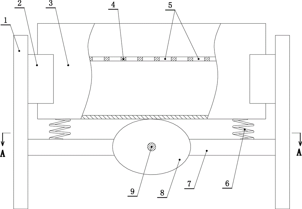
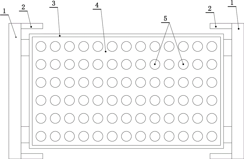
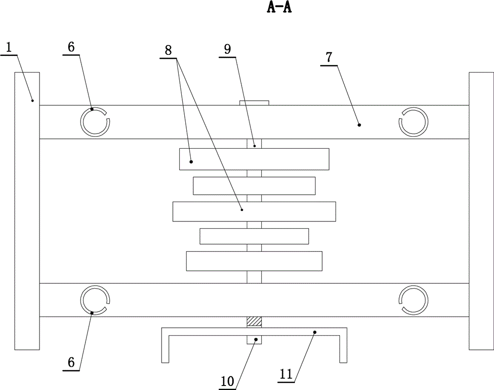
[0021] Such as Figure 1 to Figure 4 As shown, a lifting and swinging oscillator includes brackets 1 arranged opposite to each other on the left and right sides. Cross beams 7 correspondingly arranged at the front and rear are fixedly connected between the left and right brackets 1 . 1. Turntables 8 of different sizes and non-circular shapes, wherein the turntables 8 are one or more of ellipse, triangle or rectangle. The rotating shaft 9 is connected with the beam 7 for relative rotation, and the rotating shaft 9 is fixedly connected with the turntable 8 , and the intersection point between the turntable 8 and the turntable 9 deviates from the center of the turntable 8 . One end of the rotating shaft 9 is connected...


PUM


Abstract

The invention provides a lift rocking shaker. A front cross beam and a rear cross beam which are correspondingly arranged are fixedly connected between a left support and a right support, multiple non-circular rotary discs are connected between the front cross beam and the rear cross beam through a rotary shaft in a relative rotation mode, the rotary discs are arranged side by side, and the sizes of the rotary discs are different. The rotary shaft is connected with the cross beams in a relative rotation mode, the rotary shaft is fixedly connected with the rotary discs, and one end of the rotary shaft is in transmission connection with a rocking bar. Vertically-arranged springs are fixedly connected to the cross beams, the upper ends of the springs are fixedly connected with hollow test tube containing boxes with upward openings, the test tube containing boxes are erected on the rotary discs and located between the left support and the right support, shelves are fixedly connected to the interiors of the test tube containing boxes, and multiple test tube penetrating holes are longitudinally and transversely formed in each shelf in rows. The rotary discs are one or more of ovals, triangles and rectangles. The intersections of the rotary discs and the rotary shaft deviate from the centers of the rotary discs. Baffles are fixedly connected to the inner sides of the supports, and the test tube containing boxes are located in the regions defined by the baffles. The baffles are triangular or rectangular or trapezoidal.

Description

technical field [0001] The invention relates to a medical device, in particular to a lifting and swinging oscillator. Background technique [0002] In medical practice, vibration operation is required in many cases, for example, inspectors oscillate samples, nurses oscillate after mixing solid medicine and liquid medicine, etc. Some of the current oscillating operations adopt the direct shaking of the test tube by hand, which is not only troublesome, but also has a bad oscillation effect. In order to obtain a better oscillation effect, some hospitals purchase special oscillators, but the structures are complex and the cost is high. Contents of the invention [0003] The invention aims at the deficiencies and provides a lifting and swinging oscillator with simple structure, low price and good use effect. [0004] The technical scheme that the present invention solves the problems of the technologies described above is as follows: [0005] An up-and-down swinging oscillat...

Claims


Application Information

Patent Timeline
IPC IPC(8): B01F11/00
CPCB01F31/25B01F31/265B01F31/70B01F2101/2202
Inventor 梁艳
Owner 陈晓熠
Why Eureka
Try Eureka